This thread has been locked.

If you have a related question, please click the "Ask a related question" button in the top right corner. The newly created question will be automatically linked to this question.

LM2596: About RθJC(top) and max duty cycle (ON)

Part Number: LM2596
Other Parts Discussed in Thread: TPS7B88-Q1

Tool/software:

Hi team,

I have two questions about LM2596T-ADJ/NOPB

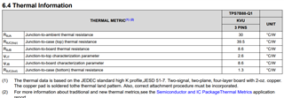
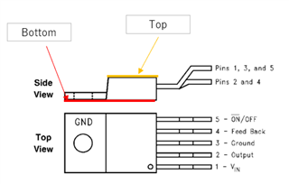
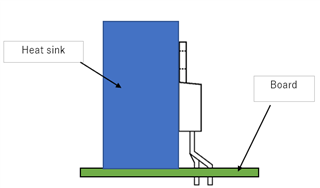
Q1. Is the thermal resistance between the junction cases correct to be calculated using the thermal resistance of "R θ JC(top) = 2°C/W" in the datasheet (7.4) when the heatsink is mounted on the back? The heat sink mounting surface is the case (bottom), but the data sheet says “Junction-to-case (top) thermal resistance”, so I am curious.

Q2. Datasheet 7.9 shows "MAX duty cycle (ON) = 100%" *Feedback pin removed from output and connected to 0 V to force the output transistor switch ON." 

In a circuit where the output voltage is set to 12V, if the input voltage drops below 12V (e.g. 8V), what is the output voltage? Is the duty cycle equal to 100%? 

Regards,

Hiromu

  • Hi Hiromu,

    1. RθJC is the thermal resistance from the operating portion of a semiconductor device to outside surface of the package (case) closest to the chip mounting area when that same surface is properly heat sunk so as to minimize temperature variation across that surface. For more information about thermal metrics, see https://www.ti.com/lit/pdf/spra953 

    2. If Vin falls below Vout, Vout will follow Vin minus losses. Eg: if Vout is set to 12V and Vin falls to 8V, Vout will actually be a little less than 8V. Duty cycle will still be 100%

    Why is FB pin being forced to 0V? The device might not function as intended since it is used to sense the regulated output voltage to complete the feedback loop.

    Regards,

    Rahil

  • Hi rahil,

    Let me ask about Q1 again.

    If the heatsink is used on the thermal pad (bottom), does the R θ JC (bottom) value need to be used to calculate the thermal resistance? How do I calculate it?

    For example, in TPS7B88-Q1, the values of R θ JC(bottom) and R θ JC(top) are different. Therefore, when attaching a heat sink to bottom, it seems impossible to calculate thermal resistance using the value of R θ JC(top).

    Regards,

    Hiromu

  • Hi Hiromu,

    Yes that is correct, we do not have a measurement for RθJC (bottom) just RθJC (top).

    Regards,

    Rahil 

  • Hi Ajani,

    Is it correct that the red and yellow lines as shown in the image below indicate bottom and top?

    When the device is implemented as shown in the figure below, how is Tj calculated? 

    Regards,

    Hiromu

  • Hi Hiromu,

    That is correct. I checked with the team and looks like you can use the RθJC of  2°C/W for calculations here. 

    For Tj calculation with heatsink please look at section 2.2 (page 7) of https://www.ti.com/lit/pdf/spra953

    Regards,

    Rahil

  • Hi Ajani,

    Thank you for checking. I wonder why can I use  RθJC of  2°C/W for calculations here? For exsample in TPS7B88-Q1, RθJC(bottom) and RθJC(top) values are quite different. Could you tell me reasons for that?

    Regards,

    Hiromu

  • Hi Hiromu,

    I suspect it's due to deferent definitions of what "top" is based on difference in packages.

    Regards,

    Rahil