Other Parts Discussed in Thread: CSD15380F3, BQ25570,
Tool/software:
Hi,
I've been investigating options for digitally selectable resistor divider networks for the VRDIV/VOUT_SET to selectively change the output voltage of a buck converter.
One promising option is the CSD15380F3 N-channel NexFET, which has an extremely low leakage current (IDSS) when VDS is much less than 16V. From my simulations, this setup shows a VRDIV pulse taking about 100-200 microseconds to reach a steady state (not a perfect square pulse shape) for a low-side resistor divider switch.
I have a few questions:
1. Where in the VRDIV pulse (~2ms) is the VOUT_SET voltage referenced?
2. Is it an average of the entire pulse, or is the reference taken at a single point near the end of the pulse?
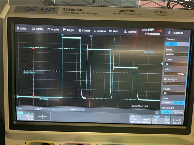
3. The BQ25570 datasheet example waveforms for VRDIV show only two pulses (VSTOR and 2/3*VSTOR). However, when probing TP7 of the BQ25570EVM-206, there are three pulses. What is the purpose of the third pulse (see attached photos)?
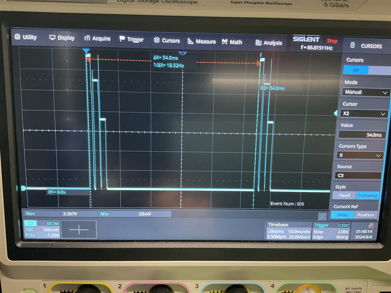
4. According to the documentation, the VRDIV cycles every 64ms. However, on the EVM board, it is only 54ms (confirmed on multiple EVM kits). Why is the VRDIV process repeating 10ms faster than specified in the datasheet?
I would greatly appreciate any clarity you can provide on this topic!
Thank you!