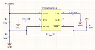
Other Parts Discussed in Thread: TPS3842-Q1, TPS3840, TPS3842, TPS3808
Tool/software:
Hello,
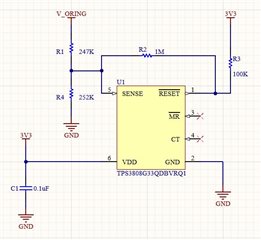
We are using TPS3840DL32DBVRQ1 in one of our design, I have attached the image of our design to review, as per design we are using the EC25 microcontroller. When the EC25 is in power-down mode, it can be turned on to normal mode by driving the PWRKEY pin to a low level for at least 500ms.
For this, we have designed an ON-OFF circuit (refer to the attached image). V_ORING is a supply voltage that may vary from 7.4V to 12V. We are planning to use a resistor divider to provide VDD to the TPS3840DL32DBVRQ1. Is this approach acceptable?
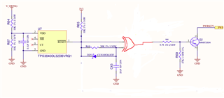
When VDD rises from the threshold (6.8V), the RESETN will go high. As a result, one input of the X-OR gate will be high and the other will be low for the capacitor charge time (660ms). Therefore, the output of the X-OR gate will be high for 660ms. This will generate a 660ms pulse on the transistor’s base, which will subsequently drive the PWRKEY pin of the EC25 low for 660ms.
When VDD goes below 6.4V then the RESETN will go low, as a result one input of the X-OR gate will be low but as we have provided D25 diode it will provide the discharge path to reduce the discharge time. as we do not require pulse for turning off.
So can you please review the design and please confirm if our approach is electrically and functionally correct?
In the attached image we are using 74AUP1G58GW,125 IC as an X-or gate.
Regards,
Nitesh