This thread has been locked.

If you have a related question, please click the "Ask a related question" button in the top right corner. The newly created question will be automatically linked to this question.

CSD19535KTT: thermal parameter, junction temperature calculation and measurement

Part Number: CSD19535KTT

Tool/software:

Hi,

To sum up from CSD19535KTT: CSD19535KTT thermal calculation - Power management forum - Power management - TI E2E support forums,

Rθjc is Junction to Tab thermal impedance, could you confirm my model?

thermal model

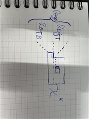
J stands for Junction,
T for Tab,
B for Board

Is Rθjc of 0.4°C correct to measure Junction temperature from the top of the Tab?

NB: the FET is solder to a copper inlay of 20mm x 25mm x 3mm

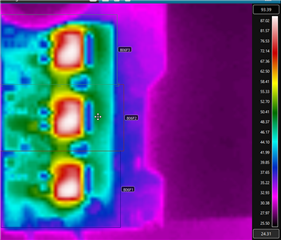
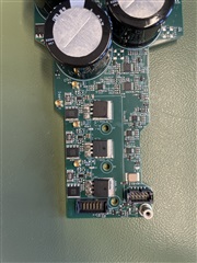
My goal is to survey the junction temperature during a stress test with a thermal camera on top (please see attached pictures IR and visible picture of the setup (3 FET on copper inlay 12mm apart)).

Kind Regards,

Vincent

  • Hello Vincent,

    Thanks for your interest in TI FETs. For the D2PAK package, Rθjc, thermal resistance from junction-to-case, is defined from the junction to the bottom of the tab (drain) or Rθjc(bottom). This is the main path to remove heat from FET and spread it into the PCB. TI does not specify Rθjc(top) which is the thermal resistance from junction-to-top of the plastic case. Based on earlier thermal simulations, the estimated value of Rθjc(top) ~ 30°C/W. Please see the technical article at the link below for more details on how TI tests and specs thermal resistance of our FETs. Let me know if you have any additional questions.

    https://www.ti.com/lit/ta/ssztb80/ssztb80.pdf

    Best Regards,

    John Wallace

    TI FET Applications