This thread has been locked.

If you have a related question, please click the "Ask a related question" button in the top right corner. The newly created question will be automatically linked to this question.

TPS65265: Oscillation under load

Part Number: TPS65265

Tool/software:

Hello,

I have a design based on the TPS65265 EVM, with 1V, 1.8V, and 3.3V outputs. All three outputs appear to be unstable under load, with oscillations at various frequencies in the 75kHz to 150kHz range, depending on the output. The schematic is:

For clarity, the ROSC input is driven by a separate oscillator at ~600kHz once the PGOOD is true, but this is not a factor, since the same problem exists if these parts are not populated. Note that PSM is disabled.

Here is the waveform at the LX1 pin under no load:
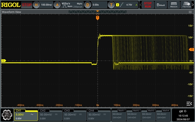
and under 2A load:

The output voltage at 2A load looks like:

The layout looks like:

Top layer:

The EVM does not exhibit these issues under the same conditions. I can't see what I am doing wrong here. Help!

  • Hi Paul,

    (1) What is the effective value of Cout you used? (Recommend check the DC bias voltage characteristics of ceramic capacitors considering the ceramic capacitor has DC de-rating.) After checked, you can compare with what EVM recommend.

    (2) Is any component/device manually soldered which might cause weak soldering quality? Or any quality issue of feedback resistor or compensation network. If you have EVM board, you can try to replace the compensation and feedback components on the EVM board to your board to whether this issue still exist.

    (3) Add a 10-100pF capacitor in parallel with bottom resistor to see any improvement.

    Thanks!

    BRs

    Lucia

  • Hi Lucia,

    I've tried to stay as close to the EVM as possible.The output caps are 22uF/6.3V X7R. I have also tried 22uF/10V X5R's I have on hand, but the issue remains.

    I have replaced all of the COMP parts, and the TPS65265 (three times now!), and the exact issue remains. I don't think assembly is the issue at this point.

    I have tried a 100pF across R16 (I assume that is what you mean by "bottom resistor", but no change. I have also tried replacing R17 with 20K and C46 with 3.9nF, but no improvement.

    I am not sure what else to try. Please advise.

    Best Regards,

    Paul

  • More information:

    I have increased the cap across R16 from 100pf to 10nF. R17 is 20K and C46 is 3.9nF X 2. The output is stable under load now, but as might be expected the transient response is poor. Here is the output voltage when cycling the load between 10ma and 2A:

    Any ideas?

  • I have been able to make this work by changing the compensation and feed forward values to match the datasheet formulas. In my case, I changed:

    C45 to 560p
    R17 to 6.8k
    C46 to 3.9n
    C52 to 100p
    R23 to 10k
    C56 to 10n
    C63 to 270p
    C64 to 10n

    I'm very surprised that these values are so different from the EVM, when I have a layout and design that is very similar to that PCB. Again, the EVM is stable with the same loads, but my duplicate of that design was not. With these changes my design is now stable. Can you explain why the compensation is so different on the EVM vs the datasheet and what is needed on my board?

  • Hi Paul,

    Thanks for your feedback. Pls kindly let me check your questions during these days.

    BRs

    Lucia