This thread has been locked.

If you have a related question, please click the "Ask a related question" button in the top right corner. The newly created question will be automatically linked to this question.

LM5022: Calculation of MOS tube power of isolated flyback power supply composed of LM5022

Part Number: LM5022
Other Parts Discussed in Thread: CSD19534Q5A

Tool/software:

HI,Team.

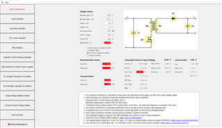
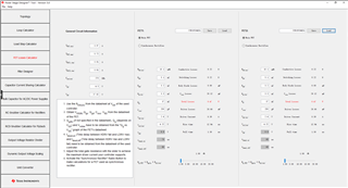
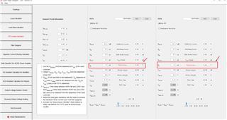
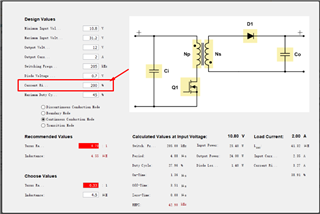
Currently, an isolated flyback power supply is constructed using LM5022, with an input voltage of 10.8 to 31.2V and an output voltage of 12V at 2A. The CSD19534Q5A is used as the switching transistor with an efficiency of 70%. The turns ratio of the isolation transformer is NP:NS=1:3. Due to a change in output power from 2A to 2.5A, the question is how to calculate the power dissipation of the switching MOSFET. Thank you.

  • Hello Sheng,

    Thanks for reaching out to us via e2e.

    Please use the power stage designer which you can download from here:
    www.ti.com/.../POWERSTAGE-DESIGNER

    First select the topology and enter your input- and output values, etc.
    The open the FET losses calculator and select the FET from the list (center top field).

    Best regards
    Harry

  • Hello Harry

    thank you for your reply.

    As shown in Figure 1 below, the red mark on the figure indicates that there is an error in the parameters?

    Because the transformer I use has a turn ratio of NP:NS=1:3, and this parameter cannot be set in the software, the duty cycle will exceed 50%. Will this affect the power consumption calculation of the MOSFET?

    As shown in Figure 2, there are two MOSFET options on the MOSFET power consumption calculation page. Are these two MOS tubes used in parallel on the primary

    side? Is the total power consumption the sum of the power consumption of the two MOS tubes?

    Does the LM5022 have a separate flyback converter calculation EXCEL document? Will this document have a more accurate FET power consumption calculation?

  • Hello Sheng,

    Red fields mean that the parameters are out of range.

    To enter a turns ratio of 1 : 3, please simply re-calculate to a ratio of n : 1. In your case this is 0.33 : 1.

    Best regards
    Harry

  • Hello Harry

    thank you for your reply.

    Are FET1 and FET2 used in parallel? Is the total MOSFET power dissipation the sum of the two?

    How to set the inductor ripple current parameter?

  • Hello Sheng,

    Please click on Help -> User's Guide to get a detailed description of all features of the Power Stage Designer.
    There you will find the following:
    The FET Losses Calculator lets the user either compare two different FETs ... (or calculate losses for the main
    FET and a synchronous rectifier in a hard-switching power stage - which s not applicable for an asynchronous topology).

    So, the FETs are not used in parallel. You can enter two different FETs and compare the losses.

    The main page shows that the actual problem is that your favorite transformer cannot be used for the given input and output voltages and the desired output current.
    Even if you set the maximum duty cycle to 30%, you will need a transformer with a lower inductance or a different turns ratio.

    Best regards
    Harry