This thread has been locked.

If you have a related question, please click the "Ask a related question" button in the top right corner. The newly created question will be automatically linked to this question.

LM25180-Q1: Flyback Transformer – T1 question

Part Number: LM25180-Q1

Tool/software:

Hi TI team,

There is no Aux widing, but to improve the customer board, the customer is reviewing the data sheet's application.

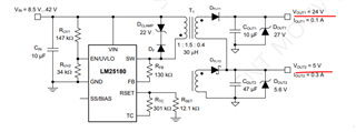
The circuit of the application is output 24V / 5V.

However, in the Flyback Transformer calculation formula, it is calculated with VOUT 19V.

1. Please explain why Vout1 is calculated as 19V.

2. If the application has an additional output of aux winding.

    OUT1 : 18V

    OUT2 : 6.7V

    Aux OUT3 : 5.7V

    Should I calculate it as Vout1 = 18V-6.7V-5.7V?

  • Hi SR,

    Thank you for posting.  It depends on how you configure the secondary windings.  For the schematic above, the two secondary windings are basically connected in series.  Therefore,

    A1.  Vout1 is the sum of the two winding's voltage, one 19V and the other 5V, to make a total of 24V.

    A2. Yes if you configure the secondary winding similarly, namely connect them in series.  In this way, winding Ns3 will produce 5.7V, Ns2 1V, and Ns1 5.6V.   Instead, you can have a winding just produce the entire output voltage rail, like Ns1 for 18V, Ns2 for 6.7V, and Ns3 for 5.7V. Then they should be independent and not connected in series.

    Hope this help.

    Regards,

    Youhao