This thread has been locked.

If you have a related question, please click the "Ask a related question" button in the top right corner. The newly created question will be automatically linked to this question.

TPS7A8101-Q1: abnormal on start up after performing high&low temp test

Part Number: TPS7A8101-Q1

Tool/software:

Hi team, 

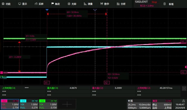
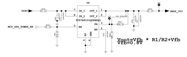
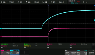
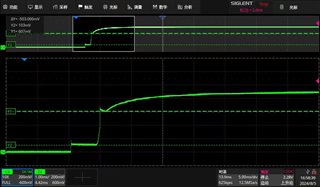
We found an abnormal phenomenon on TPS7A8101-Q1. Below is the output waveform under room temperature. CH2 is the output of TPS7A8101-Q1. We can see that the voltage is rising smoothly at start-up. 

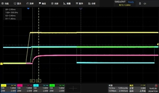
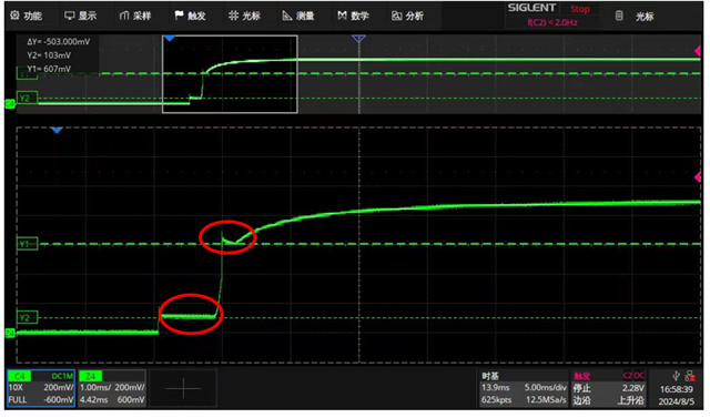
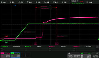
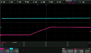
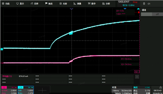
After customer perform the high and low temp test on TPS7A8101-Q1, we found that the start-up curve on output get abnormal, see below. Even we leave the DUT under room temp several days, we can also get same phenomenon on output. 

Any suggestions to debug? 

Thanks!

Ethan Wen

  • Hi Ethan,

    Does the input voltage waveform look the same in the second scope shot as the first? Can they share another waveform showing both the input voltage and the output voltage? Can they also share a schematic of their setup?

    What are the details of the high and low temp test?

    Regards,

    Nick

  • Hi Nick, 

    I have checked with customer. In abnormal waveform, there have two plateaus as below. We tried to disconnect the load from the output, then the second plateau disappear. But the first plateau still exist. Then we did the ABA test, found that the first plateau follow with the device. For the high and low temp test, purpose is to evaluate the power sequency of the whole system in both 85C and -40C. 

    For this failure unit, I suggest customer to request the FA for further analysis. 

    Besides, we have an application question would like to check with you. There have one 3.3V rail which require 100us~10ms rising time at start up. You can find their detailed requirement as below. 

    Requirement: 

    • input: 4V
    • Output: 3.3V/120mA
    • Load supply requirement
      • From 10% to 90%, the rising time should within 100us to 10ms

    Questions: 

    You can find their schematic as below. Cbypass=470nf, Cnr=4.7nf. The rising time at start-up is about 30ms. It is not match with calculated value. We would like to reduce the rising to 10ms. Any suggestions? 

    Start-up waveform: 

    Schematic: 

    Thanks!

    Ethan Wen

  • Hi Ethan,

    Do they have any waveforms of the plateau failure device with the input voltage on it as well? This looks abnormal. The temperature test does not seem problematic at a basic level, but there could be details that haven't been shared that could cause issues, such as frost build up at -40C. 

    Questions: 

    You can find their schematic as below. Cbypass=470nf, Cnr=4.7nf. The rising time at start-up is about 30ms. It is not match with calculated value. We would like to reduce the rising to 10ms. Any suggestions? 

    The feedforward capacitor (what they called Cbypass) adds a time constant to the startup as well, which is why it takes a lot longer to start up than expected. The time constant for the feedforward capacitor is the parallel resistance of the feedback divider times the feedforward cap, or 40.2k * 12.7k / (40.2k + 12.7k) * 470nF = 4.5ms, and the startup time as calculated from Equation 1 (total startup time, approximately 3 time constants) in the datasheet is approximately 8ms, so the contribution of the feedforward cap is dominating the startup. If you want to rely only on the startup time calculation, you will need to size down the feedforward cap such that the time constant is an order of magnitude less than the CNR time constant. 

    Regards,

    Nick

  • Hi Nick, 

    Please check below waveform. Any ideas would be helpful! 

    Below is the waveform with input signal. CH4=input. CH2=output

    Disconnect the load from output, waveform shows as below. CH4=input, CH2=output, CH3=EN. We can see the second plateau was gone. But first plateau still exist. The voltage level is 0.12V. 

    We tried to do the ABA, and this plateau follow with the device. 

    Thanks!

    Ethan Wen

  • Hi Ethan,

    Thanks for the new waveforms. The input voltage and EN signal both look normal, so I don't see a good reason for the abnormal behavior. I also suggest submitting for an FA. 

    Have they done the temperature test on more than one unit? Have they seen any other failures? What equipment do they use for -40C testing, and for how long do they keep it at -40C?

    Thanks,
    Nick

  • Hi Nick, 

    Yes, they found 2 units with this issue after the test. They put their board into the Champer for two hours under -40C to test the power sequency of each power rail. After about 2 hours, they took the board from the Champer. When the temperature rise to ambient temperature. They found two units with this issue. 

    Besides, they also tried with our TPS7A8101-Q1 EVM under same condition. After putting it into -40C Champer for two hours, the similar issue was observed in EVM. See below the details. 

    Conditions: 

    Input=4V, output=1.8V with 15ohm load connected. Put EVM in -40C Champer and power up for operating 2 hours. Then take it from Champer and wait for the temperature rising to ambient temp. 

    Waveform1-Before put it into -40C Champer

    Waveform 2 - after -40C operating, with no load on output

    Waveform 3 - after -40C operating, with 15ohm load

    Thanks!

    Ethan Wen

  • Hi Ethan,

    I will close this post and continue support offline. 

    Regards,

    Nick