This thread has been locked.

If you have a related question, please click the "Ask a related question" button in the top right corner. The newly created question will be automatically linked to this question.

LM5022: LM5022MM/NOPB

Part Number: LM5022
Other Parts Discussed in Thread: LM5177, LM51772

Tool/software:

Hi 

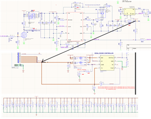
I am using LM5022MM/NOPB for a boost converter to generate 32V from 21V for charging a capacitor bank .and trying to limit the current LMP8646MKNOPB using current sense and feedback of regulator adjusting ..

The attached is the schematics ..Can you help to review the schematics ,Does this topology works ?

The current limiting circuit designed this way by controlling VFB Pin 

But when the capacitors are charged from empty to the input voltage is dips and reboots the system .. Max load that the system supports is 500mA  at 32V 

  • Hellu Justin, 

    Thanks for reaching out to us via e2e. 

    I am sorry, I could not spend time on your questions today.
    I will get back to you tomorrow. 

    Best regards
    Harry 

  • Hello Justin,

    The concept you show can theoretically work.
    But in praxis it is very tricky to adjust all components in a way that the controller will not always go into peak current limit while at the same time being able to do a proper boost.

    I would propose that you have a look at the LM5177 / LM51772 instead.
    In addition to the regular peak current control loop, this controller offers a second average current limit capability (which can be used either for the input or for the output side).

    It will disconnect the load (capacitor bank) while it is not operating, limit the current while the capacitors are getting charged from 0V to the input voltage and also limit the current when it needs to boost from 21V to 32V.
    All in one device.

    Best regards
    Harry

  • this can be tried in the next design .. but currently the problem  we face is when we charge from empty the input power dips 

    the below are the values used 

    is this soft start limitation is 10 ms is because of some internal circuit design of the boost controller ?

    can i increase the value of this capacitor ?

  • Hi Justin,

    our engineer is out of office.
    He will answer your questions on Monday.

    regards,
    Johannes

  • Hello Justin,

    I can only see the Webbench screenshot, but not he other attachment.

    Anyway. When your input voltage dips, your supply is not able to deliver enough (peak) current.
    You probably have to use usa a bigger current sense resistor and a bigger inductor to further limit the peak current.

    The soft start can be made longer than 10ms, but not too much.
    The SS pin does deliver 10uA to charge the external capacitor.
    When you use a high-quality capacitor with a very low leakage, you can go higher,
    but you must make sure that the capacitor will still get properly charged under all worst case conditions.

    Best regards
    Harry

  • what's the maximum allowed soft start time ?

  • Hello Justin,

    There is no hard limit for the soft-start time.

    As I mentioned before, it all depends on the external capacitor that you are using.
    The SS pin does deliver 10uA to charge the external capacitor.
    It is up to you to make sure that the capacitor will still get properly charged under all worst-case conditions (tolerances, temperature, aging, etc.).

    All information in this correspondence and in any related correspondence is provided “AS IS” and “with all faults” and is subject to TI’s Important Notice (www.ti.com/.../important-notice.shtml).

    Best regards
    Harry