A related question is a question created from another question. When the related question is created, it will be automatically linked to the original question.
If you have a related question, please click the "Ask a related question" button in the top right corner. The newly created question will be automatically linked to this question.
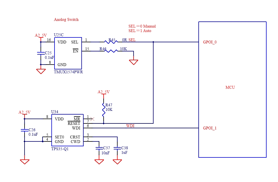
TPS35-Q1: How to design an output Latching circuit using the TPS35AA38AGA?
HI,I already have the chip TPS35AA38AGA. There is an open-drain reset output latch application.How to design an output Latching circuit using the TPS35AA38AGA?
There are ways to use discreet circuitry as well as a control GPIO to implement a latch on the output of the TPS35AA38AGADDFRQ1 device. Could you please share your schematic including the TPS35-Q1 device as well as any corresponding devices and connections that share any net with the TPS35-Q1, with this I can help to add the needed circuitry to provide a sample schematic that would include latch.
Thanks for providing feedback. Joshua is out of office today but will review once he returns on Monday. A response will be provided on 8/12 by end of day.
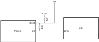
Thank you for sharing your schematic. In order to latch the reset I would recommend you add a resistor between MR and RESET, that way whenever the RESET goes low MR will be pulled low and the device will be stuck low until a GPIO pulse is provided to MR to clear the latch. For this configuration during TPS35-Q1 startup you will need to provide a GPIO high pulse to the MR so that the device does not latch on startup.
During TPS35-Q1 startup the RESET will go low, with this latch configuration you will need to provide a GPIO high pulse to the MR so that the device does not latch low on startup.