This thread has been locked.

If you have a related question, please click the "Ask a related question" button in the top right corner. The newly created question will be automatically linked to this question.

TPS7H4010-SEP: Continuous Operation in PFM Mode

Part Number: TPS7H4010-SEP

Tool/software:

Hi,

I would like to use the TPS7H4010-SEP buck converter in a very light load application. Input voltage can vary from 26V - 32V and the output is a 5V 100mA max load. Nominally the load will be 20-30mA. I expect the part to operate in PFM mode continuously - is there any concern to doing this?

The datasheet states when peak inductor current is smaller than IPEAK-MIN the part operates in PFM mode. What is the value of IPEAK-MIN for this device? Is this something that is characterized over temp or radiation? I am trying to ensure my inductor is sized correctly for the peak current seen in PFM mode.

Also, how will I know what switching frequency the device is operating at when it is in PFM mode. Is there a way to calculate this?

Thanks for the help,

Sean

  • Hey Sean,

    There is no worry about operating in PFM mode continuously.

    IPEAK-MIN is not a value that is characterized.
    Is there a reason you are trying to only stay in PFM mode?
    The device allows switching between PFM/DCM/CCM in order to allow for flexibility in operation

    The switching frequency of the device changes during PFM.
    There isn't a set frequency that you will run at, and it will change while the device is operating in the mode.

    If what you are asking for is part of a worst case analysis of the part.
    I would suggest staying in FPWM mode if possible to make things significantly easier.

    Thanks,
    Daniel

  • Hey Daniel,

    The only reason I plan to operate continuously in PFM mode is that the load requirement for this 5V output is at most 100mA. I could use a linear regulator to do this, but anything that can handle a 32V input is too large to fit in the board space I have available.

    Staying in PFM mode is preferred to take advantage of the improved efficiency versus FPWM mode.

    For a worst case analysis of peak inductor current could a transient PSPICE simulation be used plus some margin above whatever the inductor current is? It sounds like many of the parameters in PFM mode are not characterized for worst case conditions.

    Thanks,
    Sean

  • Hey Sean,

    Theoretically what would be happening to your design is it would switch between PFM and DCM for the very low currents which would be pretty similar in efficiency.

    PFM is effectively putting a hard limit on how low the peak can go, waiting until the peak gets high enough to start the next cycle.
    DCM will let the peak get lower and lower, but both have the benefit of not having negative current.
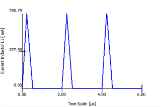
    Take the below graph as a random example:

    DCM would reduce the 755 mA peak as current got lower by reducing the duty cycle.
    PFM would keep the peak the same, while increasing the period of 2 us.
    Regardless you would have the benefit of the efficiency over CCM

    A PSPICE simulation with margin would likely be the easiest way forward for doing WCA on what you want.
    PFM being variable frequency makes it hard to define everything for WCA analysis.

    Thanks,
    Daniel

  • Ok this makes sense. To be clear - there is no way to force the device to operate in DCM mode only right? I can set it to auto mode and the chip swaps between DCM and PFM based on peak inductor current?

    Is there a typical value for IPEAK-MIN ?

  • Hey Sean,

    I am working on finding a typical value.

    I did forget to note, that all part selection should be done based on Table 8-1 in the datasheet.
    This is highly suggested because the internal compensation expects certain values externally.

    Depending on your input/output conditions the device may be forcing DCM.
    If the inductor you use makes it so the current ripple value is above 100% for all currents, this would keep the device in DCM mode.

    Thanks,
    Daniel