Tool/software:
Dear TI Engineer,
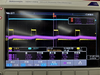
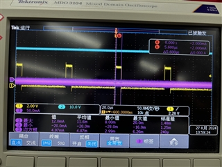
We drive the LED using TPS92365 and use the same signal in both PWM and ADIM modes. When using a frequency of 20KHz in PWM mode, the current control method is to generate a 10s PWM signal and then maintain a low level for 50ms. When the PWM duty cycle is 95%, the LED cannot work and remains dark after being lit once. However, when the duty cycle is 80%, the LED can continue to flash.
We want the LED to cycle at full power for 10ms and then stop for 30ms, but found a problem during testing. When the LED running at full power, it is given a high level and stopped at a low level. In fact, it becomes a 25Hz PWM with a duty cycle of 25%. The LED cannot work properly and will turn completely dark after being lit once. Can you give us some better suggestion for this requirement?
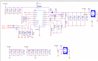
The schematic is as below:
Thanks,
Kind Regards