Tool/software:
Hi,
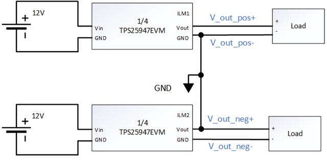
I am using a TPS2594EVM board to create an overcurrent protection circuit for a pair of power supplies connected in series.
When the kit operates in a single power rail condition, it trips at the current I set, at which point the voltage on Pin-9 (ILM) is about 0.61 V with repect to the local ground.
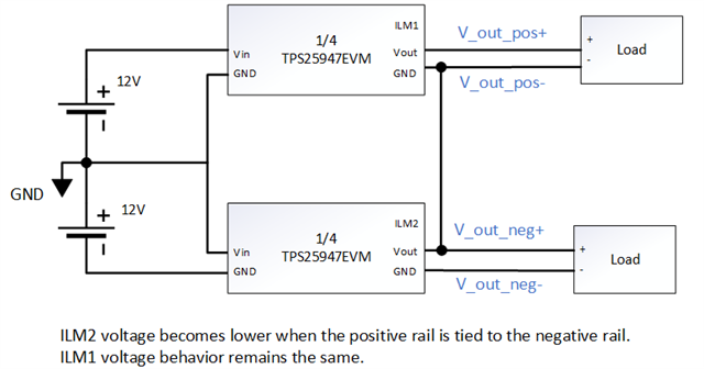
However, as soon as I connect the negative end of the protected positive output (V_out_pos-) to the positive end of the protected negative output (V_out_neg+), the voltage at Pin-9 of the negative TPS25947 would become much lower than expected. Therefore, it would require a much higher current to trip the negative rail. I am wondering what is causing the problem.
Here are some of my test data:
Given RILM of 1.65 kohms, at load current of 2.0 A:
Single supply: Vilm = 0.604V, (which make sense, because 182e-6 uA/A * 2.0 A * 1650 ohm = 0.600V)
Negative supply: Vilm = 0.228V
When the two protected outputs are not connected, there is a +25mV between V_out_pos- and V_out_neg+.
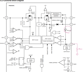
Also, how does the device sense the current going through the FETs?
Thank you!