This thread has been locked.

If you have a related question, please click the "Ask a related question" button in the top right corner. The newly created question will be automatically linked to this question.

LM74910-Q1: Ferrite beads for EMC solutions, but LM74910-Q1 stopped working

Part Number: LM74910-Q1

Tool/software:

Hi,

I have question relate to LM74910.

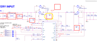
we used Ideal Diode to monitored/control Car battery of 24V.  

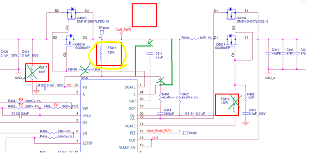
Due to EMC issue, we place a Ferrite Beads(FB415) which is BLM18SG121TZ1D from Murata in below location.

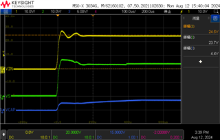
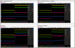
The below circuit was in normal operation, once added the Ferrite Beads(FB415 - circled in yellow color), the 24V cannot be output.

Because HGATE won't be able to turn "HIGH"

Based on LM74910 operation theory, Could you explain the reason cannot add a Ferrite Beads between external MOS and pin C & pin VS.

or any other reasons I didn't mention.

Thanks in advance,

Nick Huang

  • Hi Nick,

    Ferrite bead is not really required with this controller as it can pass the EMC standard without it.

    Can you share the part number of the ferrite bead?

    Please measure the voltage at VIN, VCAP, VS.

    Regards,

    Shiven Dhir

  • Hi Shiven Dhir,

        Please help to check below measurement results and please explain the reason and operation theory.

         We measured the 3 signals which are Vin, VCAP and VS as you required show in below,

    The all 2 of measurements condition are included the Ferrite bead(Part Number: BLM18SG121TZ1D), so the HGATE is "LOW". It meas the 24V cannot be output in those two measurement conditions.

    Signals Between Vin, VS and VCAP

    In additional, we measured extra 2 signals FLT、ISCP, compare them with Vin and VS in below,

    BR,

    Nick Huang

  • Hi Shiven Dhir,

         I forgot to mentioned that with bead or without bead(replace by 0 ohm), the measurements look the same.

    The measurement condition is bead replaced by 0 ohm.

    Bead replaced by 0 ohm.

    BR,

    Nick Huang

  • Hi Nick,

    Do you mean that when you have added ferrite bead to working controller, it stopped working. When you remove the beads, it does not recover.

    Is my understanding correct?

    Regards,

    Shiven Dhir

  • Hi Shiven Dhir,

         I mean when I have added the ferrite bead to working controller, it stopped working.

        when I removed the bead, the controller is working normally.

         But compared the waveforms between with bead and without bead, the waveforms have no big difference.

         Could you explain the the reason and operation theory?

    Thanks,

    Nick Huang

  • Hi Nick,

    Thanks for the waveforms.

    They are in a window of 600uS only. Can you share for longer duration because I do not see charge pump rising even without ferrite bead. 

    Also, I would recommend making these changes in your schematic and test again with ferrite bead.

    Short FB416, FB417, FB418 as they do not have any switching and do not need ferrite beads.

    Regards,

    Shiven Dhir

  • Hi Shiven Dhir,

    Please give me a few days. I have other urgent matters that need to be dealt with first. Please do not close this case.

    BR,

    Nick Huang

  • Hi Shiven Dhir,

        I believed our circuit is from TI User's Guide of LM74900Q1EVM Evaluation Module for LM749x0-Q1 Ideal Diode Controller. Besides, we added extra 4 ferrite beads. 

        Please give me a few days. I have other urgent matters that need to be dealt with first. Please do not close this case.

    BR,

    Nick Huang

  • Hi Nick,

    The circuit had minor errors and deviation from the user guide. They don't affect when the resistance is 0ohms but can affect the working when it is 120ohms (ferrite bead @ 100MHz)

    I will wait for your reply and will not close the case.

    Regards,

    Shiven Dhir

  • Hi Shiven Dhir,

         Thanks for the waiting.

         We measured 2 conditions, when FB415=0Ω and FB415=BLM18SG121TZ1D. Please see the below picture,

    Could you explain the the reason and operation theory between above 2 experiemnts?

    The datasheet describes once Vcap-Vs≥ 6.6V, the HGate will be turned ON.

    In addition, we did another experiment which use 10Ω resistor to instead of FB415(ferrite bead), the charge pump was working normally.

    It meas the HGate can be turned ON.

    BR,

    Nick Huang


  • Hi Nick,

    Did you make the changes in the schematic that I referred to?

    Regards,

    Shiven Dhir