This thread has been locked.

If you have a related question, please click the "Ask a related question" button in the top right corner. The newly created question will be automatically linked to this question.

UCC28180: How UCC28180 IC's Gate pin function is working?

Part Number: UCC28180
Other Parts Discussed in Thread: UCC28070, UCC28019, PMP22606

Tool/software:

Hello Everyone,

I need Ucc28180 IC's Unencrypted lib file. If any one have kindly reply to me or give the tips where it located.

1. Actually, I'm making 800W - 1000W PFC circuit using UCC28180 IC in cadence, but what i'm facing the problem was i'm not getting the GATE pulse at the o/p of 8pin.

2. I agree, what are things available on ucc28180_AVG spice model in TI website and i'm calling both olb & lib files and BOOSTCCMDCM file also added.
I create a circuit what in available on reference and I am getting the PFC boosted 380V range o/p voltage. but my intension was i need Gate pulse signal in o/p of 8 pin.

3.In TI compony provides other CCM PFC IC's also i'm facing same problem. 

4.I want to see the Gate pulse even any of this Ic ucc28180,ucc28019,ucc28070,ucc2806x series. Any possibilities are there?

Thanks Guys,

Regards

Suriya

  • You can refer to the PMP22606 design. It is a 1kW PFC design.

    https://www.ti.com/tool/PMP22606

    Please compare your schematic with this reference design to see if there is any major difference.

    You can also order the UCC28180 EVM to get yourself familiarized with the IC.

  • Thanks for your reply.

    I agree for the PMP22606 and UCC28180-EVM products all are similar to our design. Even we are going to order the UCC28180 some no.of values.

    But, kindly understand me I want see the Gate pulses in simulation time. I don't want to use your BOOSTCCMDCM converter or any coded component in simulation. I need only one was your UCC28180 olb and lib files. when I calling this files it should be provide the pulse signal to switching gate to power MOSFET. This is i want. 

    In PCB purpose, i'm sure we are going to do some R&D on our R0 Version board. Before that we able to know about the IC's o/p signal how it's acting on run time. That is our wish.

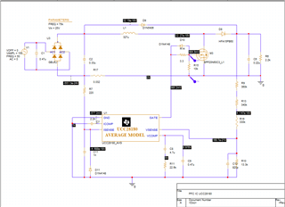
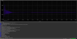
    Here, I'm attached simulation circuit and you verify that. Even you also test that circuit and kindly show the response of IC's o/p.

    i) Schematic:

    ii) Output of IC's 8th pin:

    If, your coded IC's o/p always providing the 0.9V amplitude means its not a problem. Is there any chance, i'm able to see the UCC28180's Gate signal?

    Give me CCM based PFC controller IC, also i want see the Gate signal.

    Best,

    Suriya.

  • Hello Suriya, 

    This thread is basically the same as a few other threads on the same topic of GATE pulses from UCC28180 simulation model. 

    As I had replied in an earlier thread, the UCC28180 model is an average model and does not produce gate pulses from the pin named GATE. 
    It produces a voltage which represents the duty cycle, and this voltage is fed into the "D" input of the BOOSTCCMDCM block which represents the switched node of a boost PFC, independent of MOSFET. 

    Please see my replies to your other threads. 
    Since this thread is redundant, I will close it out. 

    Regards,
    Ulrich