A related question is a question created from another question. When the related question is created, it will be automatically linked to the original question.
If you have a related question, please click the "Ask a related question" button in the top right corner. The newly created question will be automatically linked to this question.
During startup the SW pin Goes to 3.3V Without generating any waveform and VIN Remains stable at 3.3 and Vout1 at 3.3v Respectively. Could you suggest me how to start the TPS65100 with only VOUT1 Enabled so we can check the main switcher.
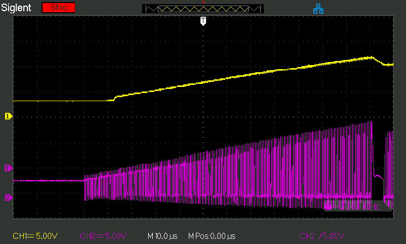
Image Showing AC Component at the Vout 1 (Main Boost Convertor)
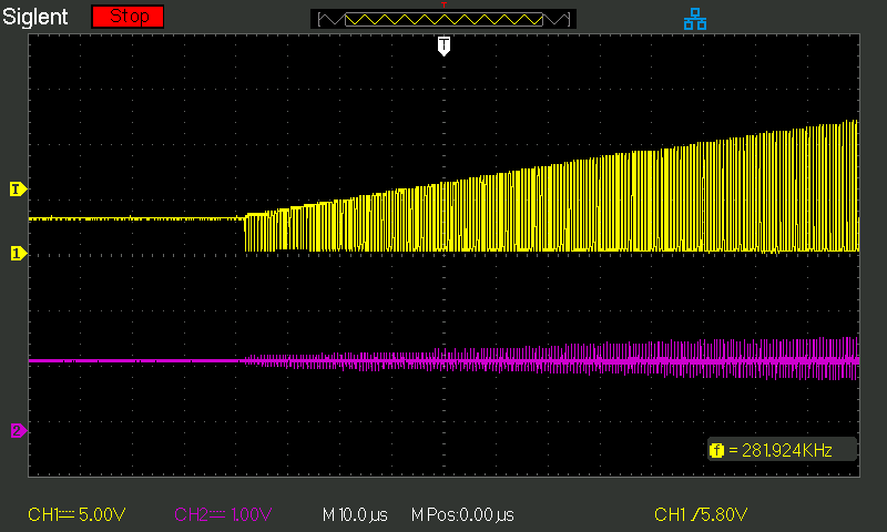
Image Showing DC Component at VOUT 1
Hi Patrick,
I can see that the switching is taking place at the SW pin. Please check the waveform as I am not getting output from the Vout 2,Vout 3 Pins and Vout 4 Is only producing -2.2v
So I have changed couple of things to make this board work. C2-/mode was shorted to ground so I have removed it from there and connected the cap directly to pin 15 and 14 Now I am getting the following readings-
REF =1.65V
Vout 1= 9.62V (connected 35 Ohms Resistance as load)
Schematic is same, I have just changed the Filter capacitors and Added a 35ohm Load at the VOUT 1Output and removed the c2-/mode pin connected to ground. Expect that everything is same.
When the Cap C15 is removed then I am getting around 1.2v at VCOMIN, I also came upon one thing that I found strange, REF is Climbing at 1.6v instead of 1.2v, What might be the problem?
Good News, I have populated a fresh board with fresh components and I can tell that I am getting better results now.
Input voltage 3.3V Current at Input side =0.043mA
VOUT1=9.946V
VOUT2= -4.78v
VOUT3= 20.2V
VCOM= 4.986v
VCOMIN= 4.85V
REF= 1.21V
These measurements are done without any load. I believe we can build fresh batches just to be sure that we have reached our goal. Next thing - To test these output under load. And Is there any way of getting 5-6 samples of TPS65100 because the TI portal is showing out of stock?


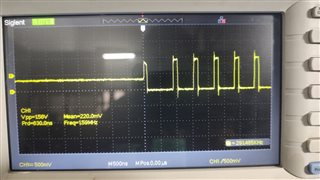 Image Showing Waveform at the SW pin
 Image Showing AC Component at the Vout 1 (Main Boost Convertor)
 Image Showing DC Component at VOUT 1