This thread has been locked.

If you have a related question, please click the "Ask a related question" button in the top right corner. The newly created question will be automatically linked to this question.

TPS92682-Q1: Formula question regarding TPS92682 input/output capacitor and inductor

Part Number: TPS92682-Q1
Other Parts Discussed in Thread: TPS92692

Tool/software:

Hi

Our customer has raised some questions about the TPS92682:

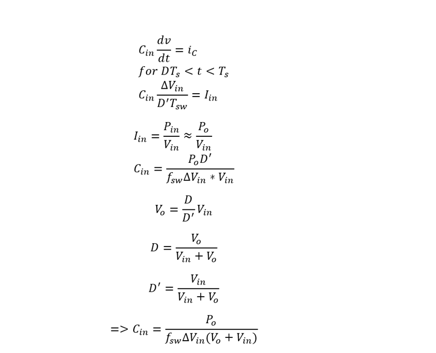
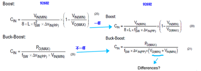
1,  Kindly wondering why the denominator in TPS92682 Buck-boost Cin formula is not fsw*▲Vin(pp)*(Vin(min)+Vout(min))? where this is the correct denominator for TPS92692. Please find the diagram below, and kindly need your suggestion here.

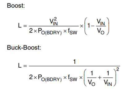
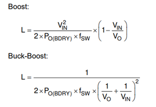
2, Normally Boost inductor calculation formula is L=(Vout-Vin)*Vin/(f*Vout*▲i), Buck-boost inductance calculation formula is Vin*Vout/(Vin+Vout)*f*▲i. However, the formula of inductance for both TPS92682 and TPS92692 are not the same as L=(Vout-Vin)*Vin/(f*Vout*▲i) . Could you please provide the detail and derivation process for the inductance and output capacitance of TPS92682?

Thank you!

  • Hi Shelly,
    I'll look into this as soon as possible
    -Daniel

  • Hi Shelly,
    I'm working on this now and I will hopefully have an answer for you later today or tomorrow.

    Thanks for your patience

  • Hello,

    The equation for the 682 provides a more conservative capacitor value and assumes Vo_min can be reduced to 0V.

    However, both these equations are only meant to satisfy the input voltage ripple and if
    PWM dimming is used, a much larger electrolytic capacitor must be placed in parallel with the X7R ceramic capacitor recommended in the data sheet. This is because an X7R ceramic capacitor has a much lower ESR than a larger electrolytic, therefore the lower ESR will dominate which will provided a much faster response time to a large inrush current which can be caused by PWM.

    Please find the derivation below:

  • Hi Daniel,

    Thanks for your response! It is my understanding that our customers can use Vo=0 to select a conservative capacitance value when selecting input capacitance for the 92682. 

    Could you please provide a detailed derivation process for inductance values of 98682 and 92692? 

    Normally Boost inductor calculation formula is L=(Vout-Vin)*Vin/(f*Vout*▲i), Buck-boost inductance calculation formula is Vin*Vout/(Vin+Vout)*f*▲i. However, the formula of inductance for both TPS92682 and TPS92692 are not the same as L=(Vout-Vin)*Vin/(f*Vout*▲i) and L = Vin*Vout/(Vin+Vout)*f*▲i.

    Thank you!

  • Hi Shelly,

    Unfortunately I do not have time to derive these equations for you, however, I am more than happy to provide you with an explanation as to why they are different.

    In our data sheet, the equations you referenced pertain to finding the proper inductance values to satisfy the boundary condition for the converters. This is the operation between DCM and CCM mode.

    Hope this helps,
    Daniel