This thread has been locked.

If you have a related question, please click the "Ask a related question" button in the top right corner. The newly created question will be automatically linked to this question.

TPS65987DDK: There is no reaction on TPS65987DDK

Part Number: TPS65987DDK
Other Parts Discussed in Thread: TUSB542, TPS65981, TPS65987

Tool/software:

Hi,

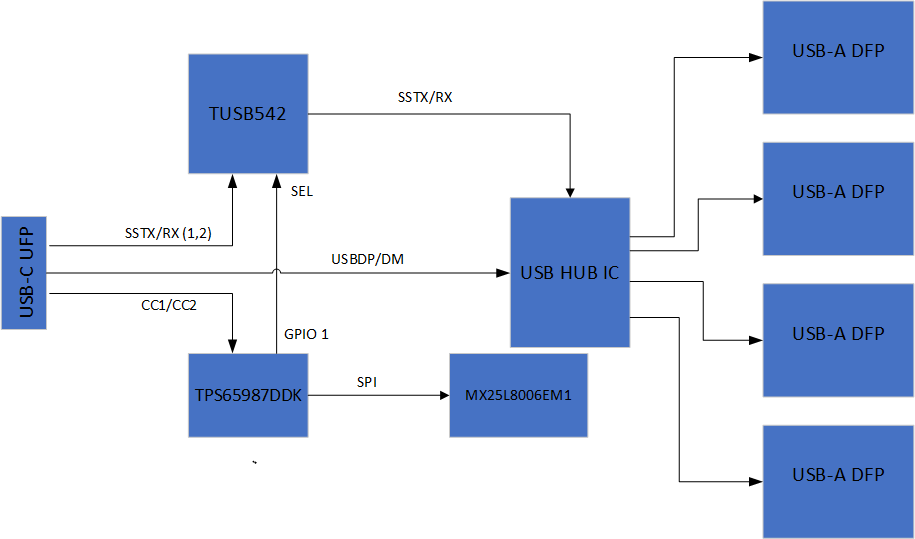
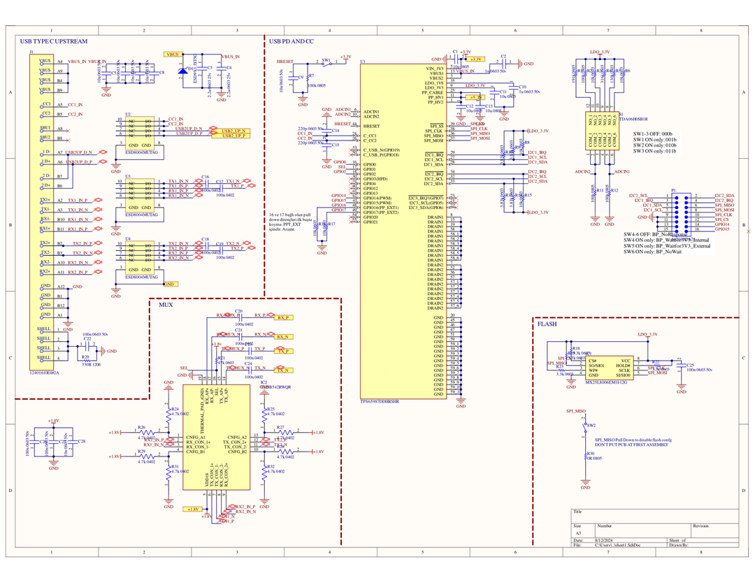
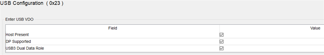
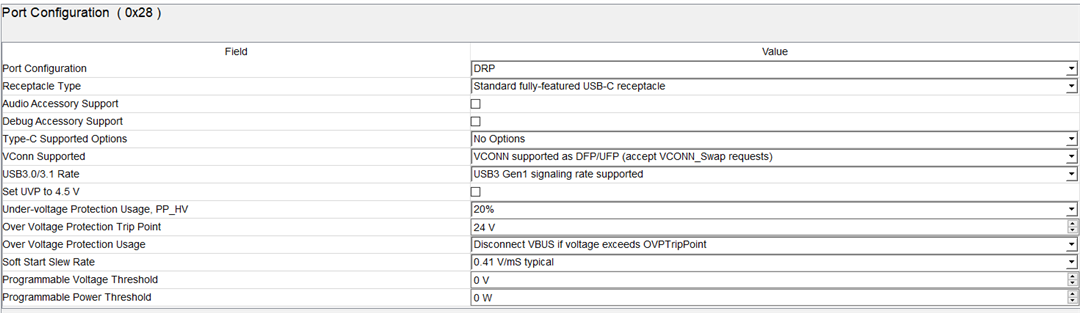
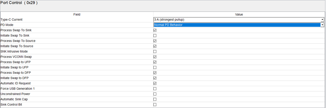
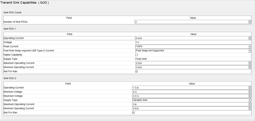
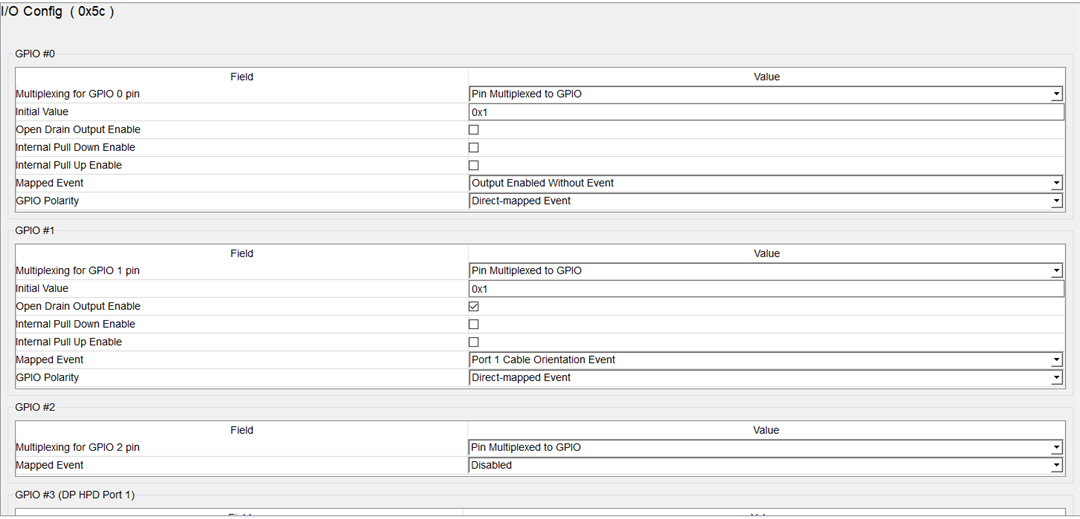
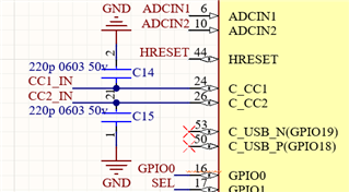
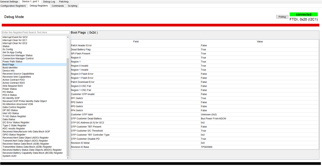
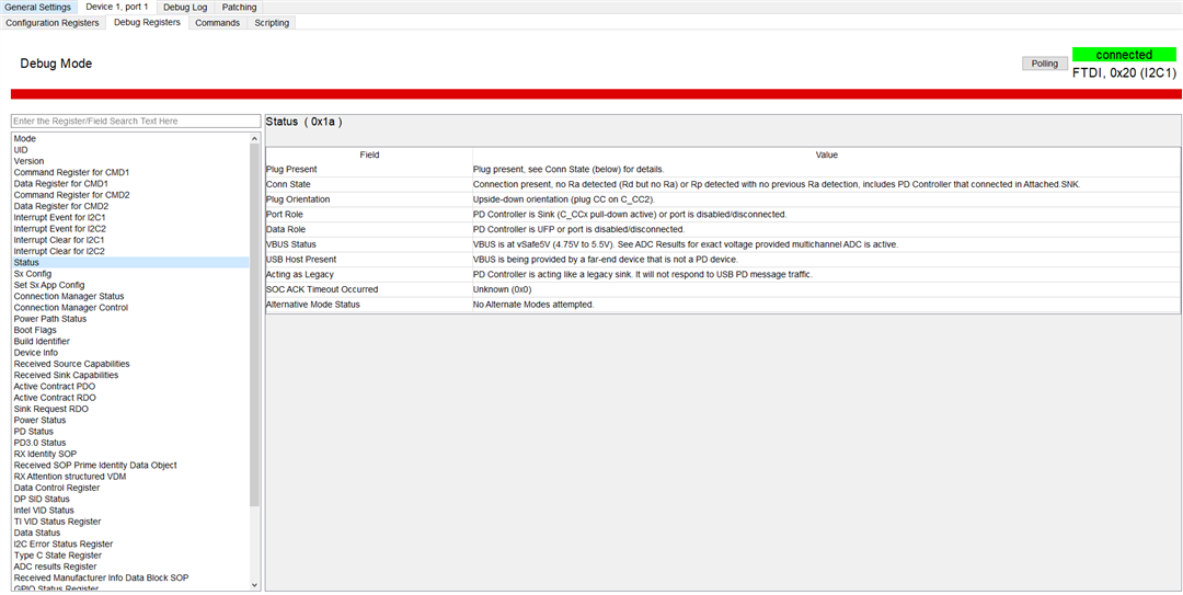
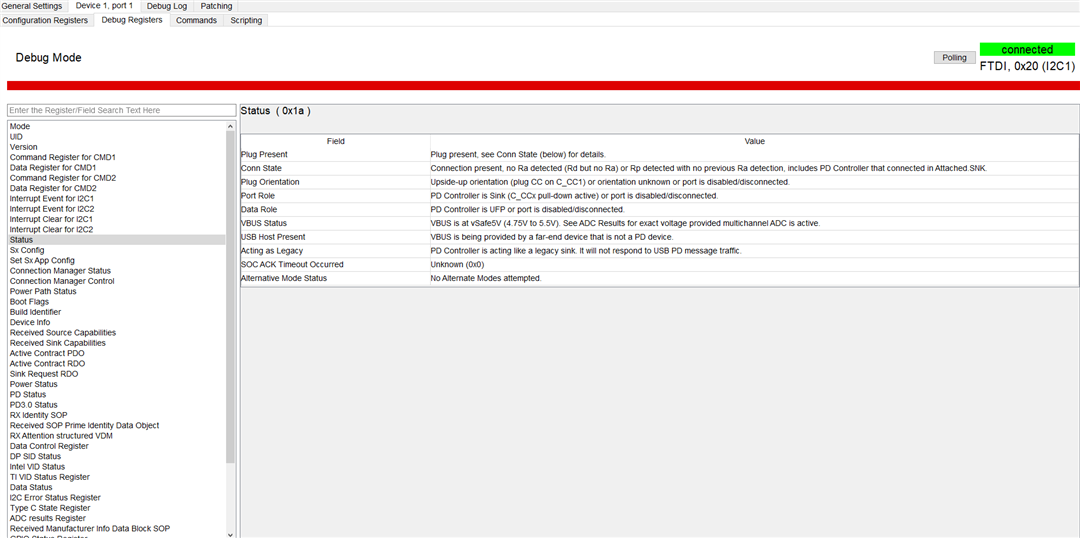
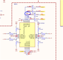
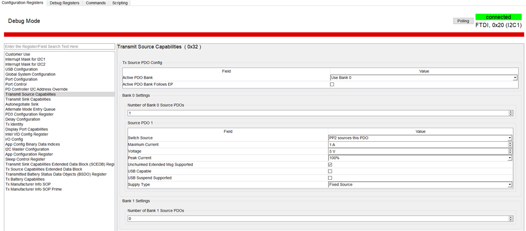
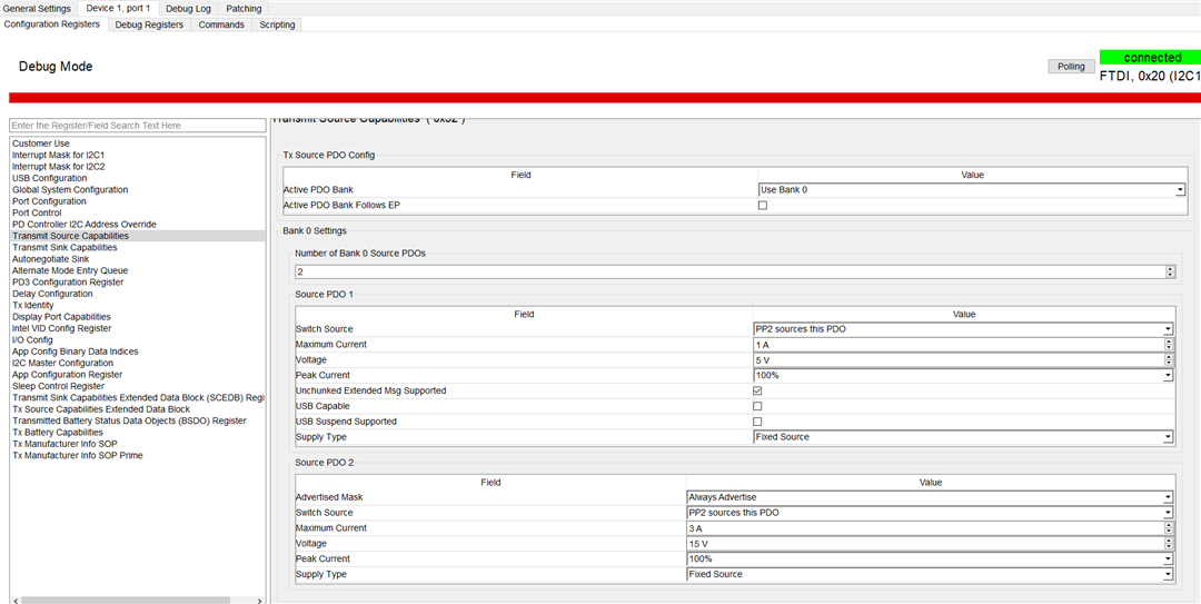
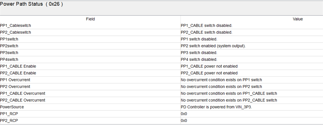
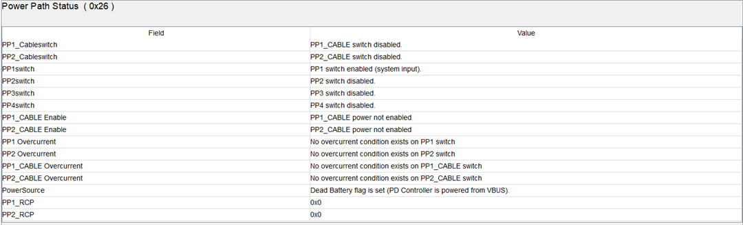
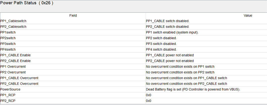
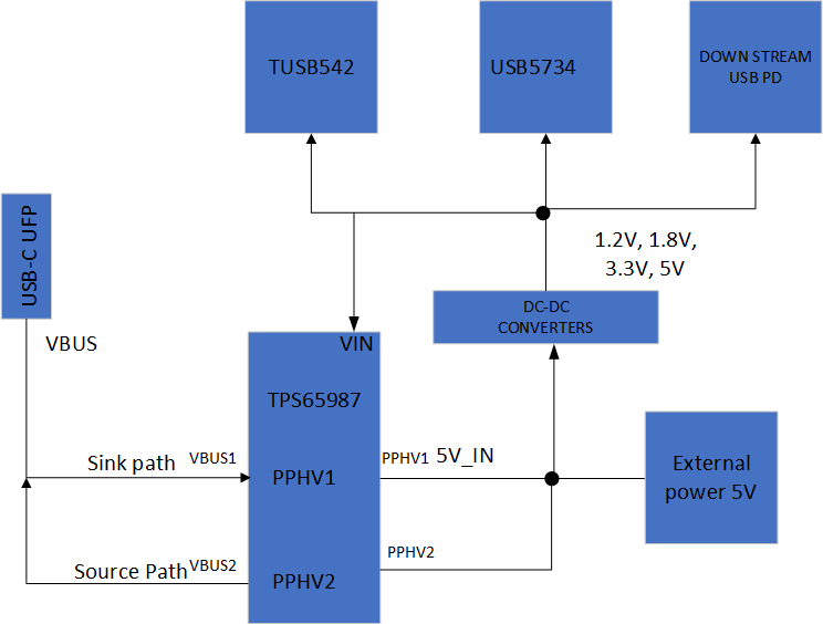
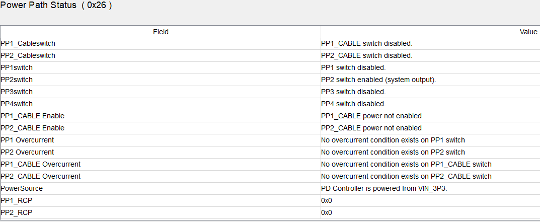
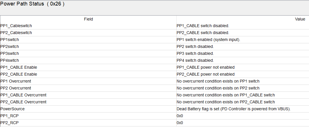
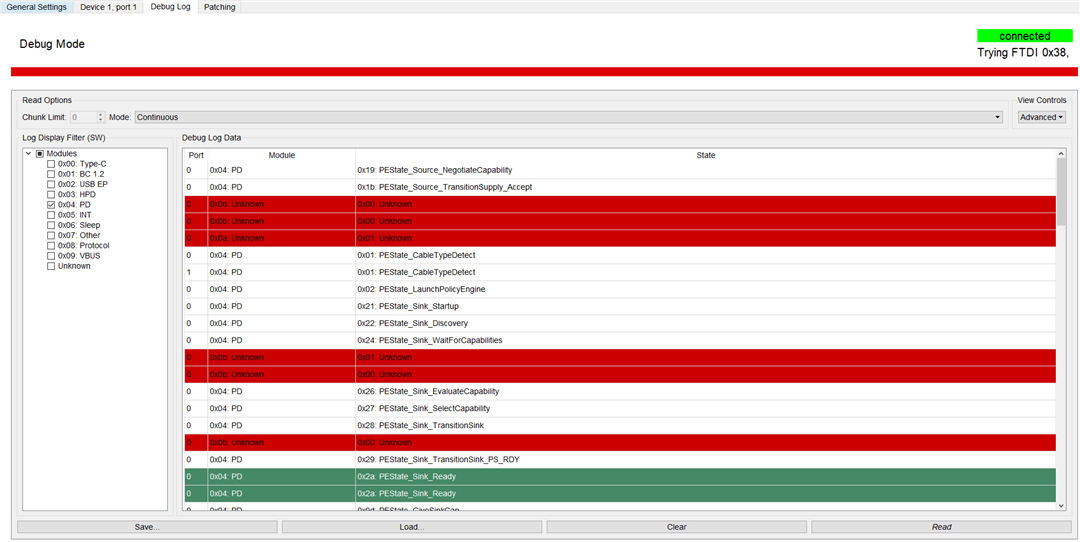
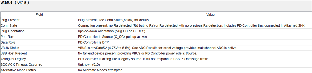
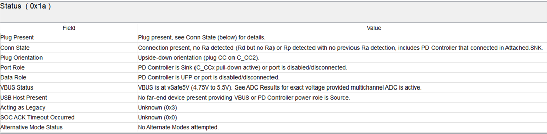
I have designed an USB HUB and manufactured it. When I plug USB devices, it works without problem. The thing is I have used TPS65987DDK and I powered the board from external supply. When I switch off the external supply, the TPS65987DDK should switch to USB power Vusb, but it doesn't. Also I configured the GPIO 1 as Cable orientation event for the TUSB542 and there is no reaction if I change cable direction. I think TPS65987DDK does not work. I've attached block diagrams and schematics down there. 

Best regards.

  • Hi Gorkem,

    Please share the .pjt file you are using to configure the PD controller. Also, which GUI are you using?

    When I switch off the external supply, the TPS65987DDK should switch to USB power Vusb, but it doesn't.

    Make sure the PD controller is configured to be source and sink, and can accept role swaps. Also realize, if you are powering via VIN3V3 and you remove power, the USB connection may drop and then reconnect and the PD controller will lose power temporarily.

    If the power is completely off, the device will need to support dead battery mode, so make sure the ADCIN config supports operation in this mode.

    Also I configured the GPIO 1 as Cable orientation event for the TUSB542 and there is no reaction if I change cable direction

    Make sure the GPIO event is configured properly. Check the output state(open drain, etc.) and make sure you are using the correct event. If you provide the .pjt you are using, I can take a look as well.

    Thanks and Regards,

    Chris

  • Dear Christopher,

    Please share the .pjt file you are using to configure the PD controller. Also, which GUI are you using?

    Unfortunately, I could not save the project, it gives an error " File "acConfigurationGui.py", line 3220, in save_json_handler". I always download bin file to upload to eeprom.

    But I added screenshots that I changed in the  TPS65981_2_6_7_8 Application Customization 6.1.4. tool.

    Also realize, if you are powering via VIN3V3 and you remove power, the USB connection may drop and then reconnect and the PD controller will lose power temporarily.

    I measured the LDO_3.3V and when I turned off the external power, USB connection drop but there is still voltage on LDO_3.3V  (because of the VBUS) so the PD controller should work and should swap the power role.

    The external power completely off but Vbus is still active and should supply power to system. In this case do I need dead battery mode?

    I attached the screenshots below. At the beginning I choose TPS65987DDK and Dual Role Port (DRP), prefers power source.

  • Hi Gorkem,

    Are you unable to save pjts at all, or is it specific to this configuration? That seems unusual.

    Have you flipped the cable multiple times? The GPIO does not react at all?

    Do you see GPIO0 go high? Or does it stay low as well.

    If you deassert it (set initial value to 0x0) and upload a new binary, does it stay low?

    I'm wondering if there is a flashing error.

    Do you have an EVM?

    What is the primary power role of your system? I can send you a basic config for testing the cable orientation event.

    Thanks and Regards,

    Chris

  • Hi Chris,

    After you told me ADCIN config, I switched it from BP_NoWait to BP_Waitfor3V3_internal and TPS65987DDK reacts it! When I turned off the external power, the circuit is supplied from Vbus without problem and I can do data transfer. But there are still problems such as cable orientation detection still no react and external power does not charge UFP device. 

    Are you unable to save pjts at all, or is it specific to this configuration?

    It is same for all, I can't save any of projects.

    Have you flipped the cable multiple times?

    Yes I did but no reaction. It shows 1.6 V for both orientation.

    Do you see GPIO0 go high? Or does it stay low as well.

    It is 0.1 V for both orientation.

    If you deassert it (set initial value to 0x0) and upload a new binary, does it stay low?

    I set it to initial value 0x0 and nothing changed. Also I tried open drain output enable and disable, still no reaction.

    Do you have an EVM

    Nope I don't have.

    What is the primary power role of your system?

    First External power and when I unplug it, the system supplied from Vbus.

    Best regards

  • I can send you a basic config for testing the cable orientation event.

    Yes please.

  • Hi Gorkem,

    If I understand correctly, the items still open are (1) Cable orientation and (2) External Power not charging UFP device?

    It is same for all, I can't save any of projects.

    Which GUI are you using? You may need update to the latest (6.1.4) or uninstall and reinstall the GUI to get saving pjts working. I'm not familiar with the issue you are seeing.

    Yes I did but no reaction. It shows 1.6 V for both orientation.

    What voltage bus is pulling up the pin? 1.8-V? 

    What is the purpose of the variable sink PDO? It looks just like a 5-V PDO? 

    See the attached binary and pjt file.

    I used these with the 6.1.4 GUI, and was able to see cable flip toggling correctly using the open drain and with a 1.8-V pullup.

    Are you sure the image is loading properly? Can you read register 0x03 from the PD controller and report what the return value is? Could you also read the Boot Flags register (0x2D).

    Thanks and Regards,

    Chris

  • Hi Chris,

    I can't see attached files. Are you sure you upload it?

    If I understand correctly, the items still open are (1) Cable orientation and (2) External Power not charging UFP device?

    Yes they both don't work. The USB power can supply power to circuit if external power is turned OFF but external power doesn't charge UFP device. I think the problem with the "not charging UFP device" is related with "Port Control" option. I think I need to change process and initiate sink and source options.

    Which GUI are you using?

    TPS65981_2_6_7_8 Application Customization 6.1.4. tool

    What voltage bus is pulling up the pin? 1.8-V? 

    what do you mean? Probably 1.8 V 

    What is the purpose of the variable sink PDO? It looks just like a 5-V PDO? 

    There isn't any special purpose. Does it affect anything?

    Are you sure the image is loading properly? Can you read register 0x03 from the PD controller and report what the return value is? Could you also read the Boot Flags register (0x2D).

    Actually I am not sure. But TPS65987 can switch the external power to USB power so it reads the eeprom I think. I attached the register screenshots.

    I couldn't find the register 0x03 there is only 0x3 register which is mode and it is APP. Also I added Status 0x1a register. It gives information about orientation. first one is first orientation and second one is second orientation.

    Best regards.

  • I just able to save the pjt file by changing the file location different than application tool folder. I attached it.

     TPS65987DDK_DRP.pjt

  • Hi Gorkem,

    It looks like I forgot to attach the files, here they are.

    https://e2e.ti.com/cfs-file/__key/communityserver-discussions-components-files/196/GS_5F00_CableOrientation.binGS_CableOrientation.pjt

    what do you mean? Probably 1.8 V 

    I circled the pull up bus for the SEL pin, it looks like 1.8-V? Just trying to make sure as you said the pin is sitting at 1.6-V.

    There isn't any special purpose. Does it affect anything?

    It should be fine, but might be unnecessary. I would recommend removing it and only having the fixed 5-V PDO if it is not needed.

    Thanks for the screenshots of the registers. It is a little confusing b/c the boot flags reports invalid regions, but also reports not patch loading failure.

    Could you also read the transmit source capabilities register and report it.

     Do it for the first project I sent and the 2nd one (_15V) and see if the transmit source capabilities register is updated with a 15-V fixed PDO.

    GS_CableOrientation_15V.pjt

    Thanks and Regards,

    Chris

  • Dear Chris,

    I ll try and let you know.

    best regars

  • Hi Gorkem,

    Thanks, will wait to hear back.

    Thanks and Regards,

    Chris

  • Dear Chris, 

    I uploaded your first bin file to eeprom, I think cable orientation is fixed because I check voltage on SEL pin, it switches between 0 V and 1.6 V when I change the orientation. But the messages did not change on Status 0x1a. 

    And there is one more new behavior. When I plug android mobile to UFP port, flash memory to one of DFP ports and give power from external supply, the charging of mobile phone is started. But the current constantly changing like fluctuating 0.088 A, 0.3 A 0.580 A again 0.088 A. this makes phone charging and not charging constantly. Also I cannot see flash memory on the android mobile. I was reading flash memory from my mobile before.

    I got a question, which option do you select when you want to save bin file? Full flash image? low region (minimal header? or low region (Full header)?

    Could you also read the transmit source capabilities register and report it.

    This is for your first bin file.

    This is for your second pjt file which is 15V.

    Best regards

  • UPDATE!!!

    Hi Chris,

    I want to update the last post. I don't know why but current flutuation is gone. It is now fixed and charges the UFP mobile phone with 1 A. But there is 2 problem now. One of is there is no data now, I can't see flash disk on my mobile phone, I was able to see before.

    Other problem is, If I turn ON external power first, after that I connect the mobile, It can charge the mobile. But If I turn OFF the external power while mobile is connected, and after that I turn ON external power again, it doesn't charge anymore.

    I've added some attachments of Power Path Status (0x26) and wrote their respective explanations below.

    1. This is the first step which I turned ON external power first, after that I connected the UFP mobile. In this case mobile phone get charged.

    2. In the second step I turned OFF the external power but mobile is still connected and mobile phone gives power to circuit.

    3. In the last step, I turned ON the external power again and mobile phone is still connected. But external power does not charge mobile anymore. I have to disconnect the mobile from circuit and connect it again to charge it again. Maybe the problem is Port Control (0x29) configurations.

    Also I did some trials with Port configuration (0x28) I change USB configuration (0x28) USB3 Dual data role and Port configuration DFP, UFP and DRP.

    dual role vs ufp-----data only
    dual role vs drp----- charge only
    dual role vs dfp --- Nothing happens with external power, when I turn off external power, data is active
    No dual role vs drp-- charge only
    No dual role vs ufp--- charge only
    No dual role vs dfp--- charge only 

    dual role vs drp vs fast role swap vs initiate swap to sink vs initiate swap to ufp--- charging with external power, data become active without external power.

    Best regards

  • Hi Gorkem,

    Thanks for checking both projects. This was to confirm the issue was not with flashing, which seems to be the case as we can see the TX Source Caps change.

    I got a question, which option do you select when you want to save bin file? Full flash image? low region (minimal header? or low region (Full header)?

    If you are using the SPI Flash, you need to use the Full Flash image in the .bin format.


    When you say "remove and turn ON external power", does this correspond to powering the VIN3V3 pin on and off?

    If/when the device loses power in step 2, we see the power paths switch from output(source) to input(sink). In step 3, even though external power is applied, we remain in the input(sink) state.

    What I think might be happening here:

    1. Typically, a phone or device will attempt to become the sink by sending a "Power Role Swap" message to the far end when the phone is a power source. If the far end does not respond, or rejects the message, the power roles will stay the same and the phone will stop attempting to change power roles.
      1. Potentially, the phone attempts the power role swap during step 2, but fails as the part does not have external power. You would need to capture a PD log during this event to confirm this behavior if possible.
      2. During step 3, once power is up, you can attempt a "SWSr" 4CC command to have the TPS65987 attempt to swap to source.
      3. At this time, you also need to check the PowerSource field in register 0x26. If the DeadBattery flag is set, the PD controller will limit it's sourcing capabilities. You may need to send a "DBFg" command at this time to clear the dead battery flag before the "SWSr" command.
        1. We set the dead battery flag when getting power from VBUS and VIN3V3 does not have power, so the PD controller is powered from the VBUS rail. During this time, we limit the source output capabilities, so it needs to be cleared once external power is applied.

    dual role vs ufp-----data only
    dual role vs drp----- charge only
    dual role vs dfp --- Nothing happens with external power, when I turn off external power, data is active

    For these three cases, can you read the Status 0x1A register? I primarily want to see the Data roles in each case.

    Please try the attached project, It is the same as the "Cable Orientation" Project, with the only change being changing the "initiate swap to xFP". If you do not have a preferred data role and want the attached device to drive the data negotiation, you can leave both "initiate swap to xFP"s un-checked. Never have them both selected for Data or Power as you may end up in a loop.

    https://e2e.ti.com/cfs-file/__key/communityserver-discussions-components-files/196/GS_5F00_SwaptoUFP.binGS_SwaptoUFP.pjt

    Thanks and Regards,

    Chris

  • Hi Chris,

    It is now working both charging and data with your latest pjt file!!  But when I turn OFF external power supply and turn ON again it doesn't charge, there is no any current consumption if I turn off and turn on the external supply.

    And there is one more problem. When I connect mobile phone, It can charge and transfer data without problem, But when I connect tablet, with same configuration, It charges but there is no data communication. When I turn off external supply, data communication appears. I checked the Status (0x1a) and Data role is "PD controller is DFP". If I turn off the external power, Data role becomes "PD controller is UFP or port is disabled/disconnected".

    At this time, you also need to check the PowerSource field in register 0x26. If the DeadBattery flag is set, the PD controller will limit it's sourcing capabilities.

    Yes you are right, I attached screenshots of PPS (0X26) DBflag is set when I turn off and stays there even if turn on again. 

    You may need to send a "DBFg" command at this time to clear the dead battery flag before the "SWSr" command.

    I sent this command and fixed! so how can I do it in configuration automatically? I also attached the PD log event during this behavior;

    1. It started with both external supply and mobile connection,

    2. Turned OFF external supply,

    3. Turned ON external supply, 

    4. Removing the mobile connection and connect it again so the charging is started again.

    PD_log_event.csv

    does this correspond to powering the VIN3V3 pin on and off?

    I mean switching OFF the external power supply. 

    1. Before I turn off the external supply.

    2. After I turn off and on the external supply.

    Best regards

  • Hi Gorkem,

    But when I turn OFF external power supply and turn ON again it doesn't charge, there is no any current consumption if I turn off and turn on the external supply.

    Can you elaborate more on the behavior here? What do you mean by current consumption, current on VIN3V3 or on the PPHV->VBUS-> phone power path.

    My understanding:

    1. Initial power up from external supply
    2. Attach phone
      1. Phone charges and data is working
      2. TPS65987 is Power Source and Data UFP
    3. Remove external power
      1. Phone stops charging and starts sourcing(?) and data is working
      2. TPS65987 goes into dead battery(?)
    4. Re-apply external power
      1. Nothing changes, no charging, still data?

    My thoughts based on understanding:

    During steps 3 and 4, the PD controller will not automatically change to Source/Charging mode. If you want the device to begin sourcing when external power is reapplied, you have some options:

    1. Use an EC to trigger a "SWSr" command, which will have the TPS65987 attempt to switch power roles from sink to source
    2. Configure a GPIO to the "Barrel_Jack_Event". Trigger this GPIO when you want the behavior to occur (maybe on external power on). On assertion, it will clear the dead battery flag and attempt a swap to source. See full description of the event in TRM.  
    I sent this command and fixed! so how can I do it in configuration automatically? I also attached the PD log event during this behavior;

    There is no way to configure the "DBFg" and "SWSr" commands to trigger automatically. You either need the I2c write or the GPIO mentioned above. The GPIO is limited to the behavior described in the TRM, so you may want to test it first.

    What tool are you using to obtain a PD log? It doesn't appear to have the info I am looking for.

    If I understand correctly, the system only gets power from External 5V or through the USB-C UFP port? If EXT5V is disabled, the port has to enter as SINK-UFP initially, which may be why the data is working. But, the initiate swap to UFP bit is set, so the PD controller should attempt a data swap even if DFP.

    You can also trigger the data role swap by sending a 'SWDF' 4CC command.

    Thanks and Regards,

    Chris

  • Dear Chris,

    I am really appreciate you to help me. I am really thank you!! 

    My understanding:

    Your understanding is completely true. 

    Configure a GPIO to the "Barrel_Jack_Event".

    I can do that, I have several GPIOs on my board. To do that, do I have to connect external 5 V directly (I will step down External 5v to 3.3V for GPIO pin) to Barrel_Jack_Event GPIO pin?

    If I understand correctly, the system only gets power from External 5V or through the USB-C UFP port? If EXT5V is disabled, the port has to enter as SINK-UFP initially, which may be why the data is working. But, the initiate swap to UFP bit is set, so the PD controller should attempt a data swap even if DFP.

    You are talking about tablet case?

    I need to explain that my main goal is the make this circuit work on Tablet. I thought that the mobile and tablet are the same and if it works on mobile then It will work on tablet. But I think they are different than each other. 

    You can also trigger the data role swap by sending a 'SWDF' 4CC command.

    When I send SWDF command, I got rejected "REJECT_CMD"

    Can I trigger data role with GPIO like "Barrel_Jack_Event"? If yes, which event should I configure?

    What tool are you using to obtain a PD log? It doesn't appear to have the info I am looking for.

    I am using same customization tool. I attached screenshot. I just read the log in continuous mode and save it.

  • Hi Gorkem,

    I can do that, I have several GPIOs on my board. To do that, do I have to connect external 5 V directly (I will step down External 5v to 3.3V for GPIO pin) to Barrel_Jack_Event GPIO pin?

    You should step down to 3.3 as the recommended max is LDO_3V3. It's up to you where to connect it. If you want the event to trigger on the power up of the external 5V, then yes. If there is some other timing you desire, you may need to connect it elsewhere.

    You are talking about tablet case?

    Yes

    When I send SWDF command, I got rejected "REJECT_CMD"

    Can I trigger data role with GPIO like "Barrel_Jack_Event"? If yes, which event should I configure?

    It may reject in these cases

    1. If the port is already DFP: check the status register Data Role before

    2. Port partner rejects the swap command: A PD log would provide this information. If the far-end rejects, there is not much we can do in terms of data swap.

    No, there is not a GPIO for the SWDF command.

    I am using same customization tool. I attached screenshot. I just read the log in continuous mode and save it.

    Oh, this log is not the "PD log". A PD log requires a special tool that decodes USB-C PD messages passed through the cable. This is a state log and does not give the information about the contract that I was looking for. Do you have a PD analyzer?

    Thanks and Regards,

    Chris

  • Dear Chris,

    If the port is already DFP: check the status register Data Role before

    Here is the screenshots of Status. First screenshot is with external power, Second screenshot is the without external power.

    Port partner rejects the swap command: A PD log would provide this information. If the far-end rejects, there is not much we can do in terms of data swap.

    So this is related with tablet it self? what if I try different brand of tablet? result will be same?

    Do you have a PD analyzer?

    Unfortunately I don't have PD analyzer.

    Best regards.

  • Hi Gorkem,

    Thanks for the screenshots.

    I gave you the wrong command to try. In this case, we want to be UFP so you should try the SWUF command, not SWDF.

    Thanks and Regards,

    Chris

  • Hi Chris,

    If the far-end rejects, there is not much we can do in terms of data swap.

    The circuit works on some kind of tablets such as Ipad pro 2022 but not working on RedMi SE 2023 tablets.  Probably It is related with power delivery specifications. 

    we want to be UFP so you should try the SWUF command

    The same result appears "REJECT_CMD".

    Thank you very much for your efforts, the problem is solved.

    Best regards

  • Thank you very much for your efforts, the problem is solved.

    Ok, I will close this thread now.

    If you have related questions feel free to re-open this thread. For new questions, please submit a new E2E thread.

    Thanks and Regards,

    Chris