Because of the holidays, TI E2E™ design support forum responses will be delayed from Dec. 25 through Jan. 2. Thank you for your patience.

This thread has been locked.

If you have a related question, please click the "Ask a related question" button in the top right corner. The newly created question will be automatically linked to this question.

TPS65023-Q1: Schematic Review

Part Number: TPS65023-Q1
Other Parts Discussed in Thread: TPS22992, , TPS65023

Tool/software:

Good Morning,

I have designed a circuit using the following TI devices:

TPS2116DRLR

TPS65023QRHARQ1

TPS22992RXPR

The use of these components was recommended by the external system designer.

The external system provides a 5V supply and a 5V battery. When on battery only, the supply keeps an RTC powered. When the main 5V supply is applied, the external system turns on the three TPS22992 power switches.

The desired operation is for the rails (voltage/battery only current/current when switches are active/minimum ramp time) are:

VDD_BATT_PS (0.8V/200uA/16mA/30us) and DVDDLO_BATT_PS (1.8V/500uA/1.6mA/100us) to ramp up in the same time, followed by the DVDD_BATT_PS (3.3V/600uA/10mA/100us)

I have attached the schematic and BOM. Single pin devices with J reference designators are test points. Two pin devices with J reference designators are jumpers to isolate the power supply from the rest of the circuit on the prototype board.

Please let me know if there is any clarifying information that I can provide.

Thanks

Frank

PowerSupplySchematic.pdf 

BOM.txt
TITLE:                 Bill of Materials
DATE:                  08/12/2024
DESIGN:                ps_only

Ref     MANUFACTURER           MPN                     Qty   VALUE       
Des                                                                      
=====   ====================   ====================   ====   ==========  
C75     Murata                 GRM21BZ71A226ME15L        1   22uF        
C76     Murata                 GRM21BZ71A226ME15L        1   22uF        
C77     Murata                 GRM21BZ71A226ME15L        1   22uF        
C78     Murata Electronics     GRM21BR71A106MA73L        1   10uF        
C79     Murata Electronics     GRM21BR71A106MA73L        1   10uF        
C80     Murata Electronics     GRM21BR71A106MA73L        1   10uF        
C81     Murata                 GRM155Z71A105KE01D        1   1uF         
C83     Murata                 GRM155R71H681KA01D        1   680pF       
C84     Murata                 GRM155Z71A105KE01D        1   1uF         
C85     Murata                 GRM188R71A225KE15D        1   2.2uF       
C86     Murata                 GRM188R71A225KE15D        1   2.2uF       
C87     Murata Electronics     GRM21BR71A106MA73L        1   10uF        
C88     Murata Electronics     GRM21BR71A106MA73L        1   10uF        
C89     Murata                 GRM155R71H681KA01D        1   680pF       
C90     Murata Electronics     GRM1885C1H512JA01D        1   5100pF      
C91     Murata                 GRM1885C1H222JA01D        1   2200pF      
C92     Murata                 GRM155Z71A105KE01D        1   1uF         
C93     Murata                 GRM155Z71A105KE01D        1   1uF         
C94     Murata                 GRM155Z71A105KE01D        1   1uF         
C95     Murata Electronics     GRM21BR71A106MA73L        1   10uF        
C96     Murata Electronics     GRM21BR71A106MA73L        1   10uF        
C97     Murata Electronics     GRM21BR71A106MA73L        1   10uF        
C98     Murata                 GRM32ER71A476ME15L        1   47uF        
C99     Murata                 GRM32ER71A476ME15L        1   47uF        
C100    Murata                 GRM033Z71A104KE14D        1   0.1uF       
C101    Murata                 GRM033Z71A104KE14D        1   0.1uF       
C102    Murata                 GRM033Z71A104KE14D        1   0.1uF       
C103    Murata                 GRM155Z71A105KE01D        1   1uF         
C104    Murata                 GRM155Z71A105KE01D        1   1uF         
C105    Murata                 GRM155Z71A105KE01D        1   1uF         
C106    Murata                 GRM033Z71A104KE14D        1   0.1uF       
C107    Murata                 GRM033Z71A104KE14D        1   0.1uF       
C108    Murata                 GRM033Z71A104KE14D        1   0.1uF       
CR2     Littelfuse Inc         SMF6.0A                   1   ?           
CR3     Littelfuse Inc         SMF6.0A                   1   ?           
J4      Keystone Electronics   5019                      1   ?           
J5      Keystone Electronics   5019                      1   ?           
J6      Keystone Electronics   5019                      1   ?           
J7      Keystone Electronics   5019                      1   ?           
J8      Harwin                 M20-9990246               1   ?           
J9      Harwin                 M20-9990246               1   ?           
J10     Harwin                 M20-9990246               1   ?           
J12     Harwin                 M20-9990246               1   ?           
J13     Harwin                 M20-9990246               1   ?           
J14     Keystone Electronics   5019                      1   ?           
J15     Keystone Electronics   5019                      1   ?           
J20     3M                     N2510-6003-RB             1   ?           
J21     Keystone Electronics   5019                      1   ?           
J22     Keystone Electronics   5019                      1   ?           
J23     Harwin                 M20-9990346               1   ?           
J24     Keystone Electronics   5019                      1   ?           
J25     Keystone Electronics   5019                      1   ?           
J26     Keystone Electronics   5019                      1   ?           
J27     Keystone Electronics   5019                      1   ?           
J28     Harwin                 M20-9990246               1   ?           
J29     Keystone Electronics   5019                      1   ?           
J30     Harwin                 M20-9990246               1   ?           
J31     Keystone Electronics   5019                      1   ?           
J32     Harwin                 M20-9990246               1   ?           
J33     Keystone Electronics   5019                      1   ?           
J34     Keystone Electronics   5019                      1   ?           
J35     Keystone Electronics   5019                      1   ?           
J36     Harwin                 M20-9990246               1   ?           
L1      TDK                    VLCF4020T-2R2N1R7         1   2.2uH       
L2      TDK                    VLCF4020T-2R2N1R7         1   2.2uH       
L3      TDK                    VLCF4020T-2R2N1R7         1   2.2uH       
R22     Vishay                 CRCW0603750KFKEA          1   750k        
R23     Vishay                 CRCW0603249KFKEA          1   249k        
R24     Yageo                  RC0603FR-074K75L          1   4.75k       
R25     Yageo                  RC0603FR-074K75L          1   4.75k       
R26     Vishay                 CRCW060310R0FKEA          1   10          
R27     KEMET                  RC0402BR-0710KL           1   10k         
R28     KEMET                  RC0402BR-0710KL           1   10k         
R29     KEMET                  RC0402BR-0710KL           1   10k         
R30     KEMET                  RC0402BR-0710KL           1   10k         
R31     Vishay                 CRCW0603249KFKEA          1   249k        
R32     Vishay                 CRCW060356K0FKEA          1   56k         
R33     Vishay                 CRCW0603249KFKEA          1   249k        
R34     Vishay                 CRCW060356K0FKEA          1   56k         
R35     KEMET                  RC0402BR-0710KL           1   10k         
R36     KEMET                  RC0402BR-0710KL           1   10k         
R37     KEMET                  RC0402BR-0710KL           1   10k         
R38     KEMET                  RC0402BR-0710KL           1   10k         
SW1     C&K Components         KT11P2JM34LFS             1   ?           
U3      Texas Instruments      TPS2116DRLR               1   ?           
U4      Texas Instruments      TPS65023QRHARQ1           1   ?           
U5      Texas Instruments      TPS22992RXPR              1   ?           
U6      Texas Instruments      TPS22992RXPR              1   ?           
U7      Texas Instruments      TPS22992RXPR              1   ?           
TOTAL                                                   89               
=====   ====================   ====================   ====   ==========  

  • Hi Frank,

    I am only able to comment on the PMIC connections to the TPS65023-Q1,
    so you may need to create another thread under the TPS22992 part number to have the device expert for power switches review those connections.

    As for comments/questions I have:

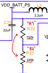
    • What is the intended output voltage level for VDCDC1? 0.8V? 
      I believe the values of R22 and R23 for this voltage divider should be switched with each other to get a V_OUT of 0.8V


    OR If using I2C to configure DEFDCDC1 (DEFCORE register, address 0x06), then this entire voltage divider should not be needed at all.

    • May I know why DCDC3_EN is connected to a voltage divider? It should just be directly connected to any HIGH signal.
    • If VRTC is not being used, please connect at least a 100 nF capacitor and do not leave floating. 
    • Minor comment: Note that the direction of PWRFAIL and RESPWRON pins should be outputs, not inputs

    Best Regards, 
    Sarah

  • Hi Sarah,

    Thank you for finding those issues. I will implement your suggested changes.

    I need channel 3 to begin its startup sequence after channels 1 and 2 ramp up. Ideally, I would have used a power good signal from one of the other channels. But this chip does not have those signals available on pins. Unfortunately, the external system will not be able to interface with the I2C.

    I have set the divider to reach the 1.3Vih threshold of DCDC3_EN when the 1.8V rail is at approximately 1.6V.

    If there is a better way to do this, I’m open to change.

    Thanks

    Frank

  • Hi Frank, 

    That should be fine. I typically see a RC circuit used to cause a delay, but if you are not worried about the particular time between the startups, and just the general sequence, I think what you have is okay. 

    Best, 
    Sarah

  • Hi Sarah,

    A more deterministic sequence would be preferred. I see that using an RC circuit in this way is mentioned in the datasheet. Are there any examples? 

    Thanks

    Frank 

  • Hi Frank, 

    I wasn't able to find a reference design example,
    but here is an applications note that goes into depth on designing RC circuit for a precise startup time:
    https://www.ti.com/lit/ab/slvaea3/slvaea3.pdf
    (It refers to a specific buck converter, but the same principle can be applied to the PMIC EN pin)

    Best Regards,
    Sarah

  • Hi Sarah,

    That is a fantastic reference! I have updated the schematic with your suggestions and calculated that DCDC3_EN will reach 1.3V in 751us-936us. If my understanding of the TPS65023 is correct, this means that the third rail will start after the first and second have completely ramped up. Please let me know if that is not the case.

    Thanks!

    Frank

     PowerSupplySchematicV2.pdf

  • Hi Frank, 

    The updated schematic changes look great to me. 

    The calculations also look correct. 

    Soft start for DCDC1&2 is about 750 us
    So yes, the RC delay (approx. 843 us, or 751 us - 936 us) will make the DCDC3 begin its startup after the other two rails have already completely ramped up.

    Best Regards, 
    Sarah

  • Hi Sarah,

    Thank you for all your help!

    Frank

  • You're welcome! Glad to be of help. 

    Sarah