This thread has been locked.

If you have a related question, please click the "Ask a related question" button in the top right corner. The newly created question will be automatically linked to this question.

UCC5870-Q1: Does the IC support default operation without any SPI configuration? It always output fault signal once powered on.

Part Number: UCC5870-Q1
Other Parts Discussed in Thread: UCC5880-Q1, UCC21750

Tool/software:

Hello,


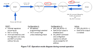
I am trying to utilize UCC5870-Q1 as a SiC module driver. Our requirements are pretty simple, it should output gate drive signal once we provide it with INL and INL.


However, the IC always output fault signals (both nFLT1 and nFLT2 are low) once powered on. I haven't used any SPI configuration yet. but I would like to know if the IC can operate without any SPI configuration? If so, is there anything special I need to pay attention to so that no fault is triggered?


Thank you.


Best Regards,

  • Hi Bin,

    UCC5870-Q1 cannot be used without SPI.

    Make sure all the unused pins are tied to known state as mentioned in the datasheet. Also, you mean, INP and INL correct?

    Also attaching a configuration guide for UCC5870-Q1 below:

    Have you considered our latest UCC5880-Q1 with higher CMTI rating and more configurability?

    Please click the green resolved button if it does, if not feel free to ask further questions.

    Best,

    Pratik

  • Hi Pratik,

    Thank you for your reply. Yes, we will use the advanced functions later, but our top priority right now is to make it to successfully drive the module.

    The link you provided cannot be opened. Could you please send it by email, to binli007@vt.edu?

    Please find our configurations of UCC5870-Q1 below.

    Vcc1 - 5V

    ASC_EN - GND1

    nFLT1 - floating

    nFLT2 - floating

    ASC - GND1

    CLK, nCS, SDI,SDO - floating

    VCC2 - 18V

    AI1 to AI6 - GND2

    VCECLP - VEE2

    VEE2 - -4V

    Do you see anything wrong with this configuration? 

    Both INP and INN are grounded and once Vcc is up, the IC just output fault signal.

    Best Regards,

    Bin

  • Hi Bin,

    Apologies for the confusion (edited my previous response). I misunderstood your question for UCC5880 which can be used without SPI (but not recommended) vs UCC5870 which cannot be used without SPI because you need to send commands to enter ACTIVE mode, the detailed procedure is mentioned in the datasheet SPI section.

    The document I sent to you should also be on the ti.com page for UCC5870. Please feel free to ask any follow up questions you might have.

    Best,

    Pratik.

  • Hi Pratik,

    Thank you for the clarification. Could you please direct me to the document that explains how to enter the active states? I checked the datasheet, but it is very vague about it. Are there any application notes that can walk me through the process?

    Also, is there any simple example code that I can directly use to program the driver (enter the active states)? I found one, which is designed for UCC5870QEVM-045. But It is a three-phase system and pretty complicated.

    Thank you.

    Best Regards,

  • Hi Bin,

    You would have to send CFG_IN command first to enter configuration 2 mode and then send DRV_EN command to enter ACTIVE mode.

    We acknowledge that the one provided for the EVM you mentioned is pretty complicated given that's designed for a HEV/EV traction inverter system which are very complicated as well.

    Given the complexity of device and lack of software support, unless you need the extensive monitoring features, I really recommend using UCC21750 which is a 10A driver, has miller clamp, DESAT protection, and an analog sense channel. UCC5870 seems like a more complicated part for the application you have described.

    Best,

    Pratik

  • Hi Pratik

    Thank you for your instructions. We will try it out.

    Currently, we don't need the extensive monitoring features, but we do need large driving current to speed up the switching. UCC21750 is easy to use but the driving capability is not enough.

    I will let you know if we can successfully program the driver.

    Best Regards,

  • Hi Bin,

    Sounds good. Looking forward to hearing from you. You can use external current buffer circuit for UCC21750 if 10A isn't enough. Please see section 9.2.2.8 (page 42) of UCC21750 datasheet for more details.

    Best,

    Pratik