This thread has been locked.

If you have a related question, please click the "Ask a related question" button in the top right corner. The newly created question will be automatically linked to this question.

BQ76952: Problems with cell meaurement Cell11 and Cell12 in 13S application

Part Number: BQ76952
Other Parts Discussed in Thread: BQSTUDIO

Tool/software:

Hi Ti Experts,


We are using the bq76952 BMS IC in one of our projects in host-controlled-mode for a 13S6P E-bike application (1600Wh).

The application was designed some years ago.


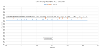
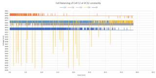
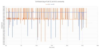
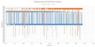
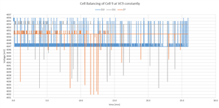
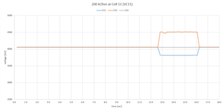
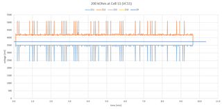
During our customer's test, we sometimes see that the bq measures a lower value for cell 11 and a higher voltage value for cell 12. After a shutdown/Reset it works fine again.

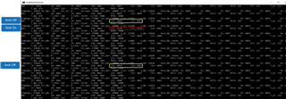
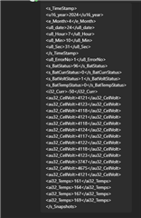
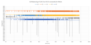
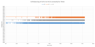
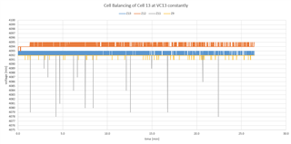
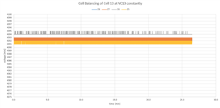
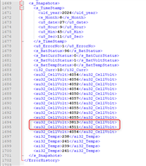
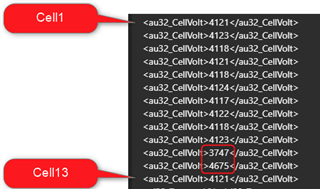
In the following snapshot you can see the cell voltages from Cell1 to Cell 13.

The customer charged the bike in the evening. At the next morning after starting the bike the measurement above was taken.

After a restart the voltage measurements were equal again.


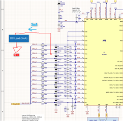
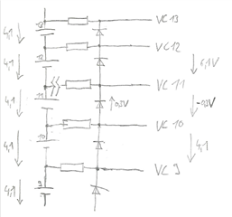
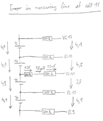
The schematic looks like this:

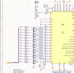
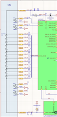
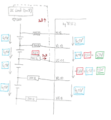
Could it be a problem that the VC14 to VC16 is shorten together or could this be the issue for our behavior?

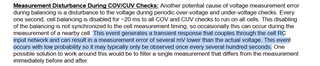
Now we know that we should do the wiring like it is written here: 

https://e2e.ti.com/support/power-management-group/power-management/f/power-management-forum/1176908/faq-bq76952-connecting-battery-cells-to-the-bq769x2-family-of-monitors


But about 4 years ago I think we did not know.

Thanks for helping us.

Klaus

  • Hello Klaus,

    Shorting VC14 to VC16 could be causing this issue potentially as certain cells should always be connected to actual cells. I would look at Table 16-3 Terminating Unused Pins in the BQ76952 Datasheet for recommendations on what to do there.

    Best Regards,
    Alexis 

  • Hi Alexis,


    Thanks for your answer.


    1. When could this issue occur?
    2. Is it while cell balancing?
    3. Is it while measuring the Cell Voltage of Cell 11?
    4. Could there be an internal damage of the bq76952 which cause a current flow into the bq (internal protection diodes,...)?


    I have made some theoretical and practical tests:

    If I draw 3mA current from the VC11 connection to GND, the behavior occurs.

    I have done this as you can see in the following sketch:

    In the next sketch you can see the corresponding the calculation:

    In the following screenshot you can see the practical test with our logging tool:

    I am looking forward to your answers.

    Thanks in advance.


    Regards, Klaus

  • Hello Klaus,

    Cell balancing is a likely time when this issue occurs as it is part of the reason why Cell 16 should always be connected to an actual cell. This forum link: BQ76952 Why Cell Inputs 1,2, and 16 Should Always Be Connected to Actual Cells explains this well.

    Section 4.1.1 Voltage Measurement Schedule in the
    BQ76952 Technical Reference Manual also describes the voltage measurement process and how Cell 16 is used to do so.

    While internal damage is possible, I would not jump to that conclusion based on the other measurement readings you are seeing.

    Best Regards,
    Alexis

  • Hello Alexis,


    Thanks for your answers.


    In this thread   has written If cell blancing is not in use it is not critical:


    https://e2e.ti.com/support/power-management-group/power-management/f/power-management-forum/1131000/bq76952-the-connection-demand-of-bq76952-when-connecting-fewer-batteries/4211011?tisearch=e2e-sitesearch&keymatch=bq76952%2525252520cell%2525252520connect#4211011


    Do I understand right that this is the only way for us to solve our problem without changing the schematic?


    Is there a way to reproduce this behavior? I have logged over days and cannot reproduce this. Only If I do like I written above.


    Thanks a lot.


    Regards, Klaus

  • Hello Klaus,

    Do you know if this only occurs when cell balancing is enabled?

    Best Regards,
    Alexis

  • Hello Alexis,


    Thanks for your answer.


    No I do not know when it happens.


    I only have a snapshot error history from the MCU:

    And I can't reproduce it here in the company.


    I also think that there is no reason to start balancing. The Balancing is managed by the bq and should start if there is a disbalance of more than 40mV.

    The battery I have here is well balanced. When no charge current is flowing there is a difference of max. 8mV. While charging with about 5A the max difference is lower than 20mV. So I think in this case there is no need to balance.


    Tanks a lot for your help.


    Regards, Klaus

  • Hello Klaus,

    There is also a chance it could be a loose wire/connection there or some additional resistance that is added there.

    Best Regards,
    Alexis

  • Hello Alexis,


    Thanks for your answer.


    I do not think that it is a loose of a wire. I don't think it's a loose connection. If this happens, the values will be much higher or lower. If I disconect the Cell 11 the measurement values go below 0V (in the screenshot it is 65478 because of the datatype conversation). The measurement of Cell 12 go above 6 V.

    And then the Open-Wire detection is asserted. So the values are much higher than in our case.


    I still have to test what an additional resistor can do. But I think that there must be a second error, because I think the measurement is only affected if current flows in the measuring line.


    Thanks for helping us.


    Regards, Klaus.

  • Hello Klaus,

    Please let me know the results of your testing when you do. 

    Best Regards,
    Alexis

  • Hello Alexis,


    If I do disconnect the Cell 11 from the battery, it looks like this:

    Because of the disconnetion at cell11, the bq measures about -0,3V between VC11 and VC10. Also the bq measure betwenn VC12 and VC11 6,1V.

    In theory, around 8.5V should be measured between VC12 and VC11. Please take a look at the following:

    If I measure with a voltmeter I can see a short time a voltage greater 7V. Than the voltage goes to 0V. I think because of the impedance of the voltmeter I can not measure 8,5V. Also the bq can not measure it.

    So a loose / disconeted cell is not our problem. The voltage differences are much higher than in our issue.


    Do you have other suggestions?

    Is it possible that the open-wire check can cause a current of about 3 mA?

    Thank you very much in advance.


    Regards, Klaus

  • Hello Klaus,

    Thank you for sharing your results. It looks like a fully open wire might not be the issue, but there is still a chance it could still be a
    brief loose cell connection that could cause a smaller change in those values.

    Is this voltage difference in Cell 11 and Cell 12 only happening once before you reset/shutdown the part or does it still occur after you shutdown/reset the part? 

    While an open-wire check draws current, I do not think it should be drawing 3mA.

    Best Regards,
    Alexis

  • Hello Alexis,


    Thanks for your answer.


    I have to check what happens if what happens if there is a brief loose of cell conection.


    We know from our customer that if the voltage difference occurs, it remains for minutes and goes away again without a reset or shutdown.


    I do not know if a Reset/shutdown helps. I would like to test it, but I can not reproduce this behavior.


    Yesterday I have got a test firmware from our firmware developer. With it I can start balancing via command. Yesterday I have balanced the cell 11 for about 2 hours constantly without any incidents.


    I don't know what else to test. Do you have any other idea?


    Thanks for helping us.


    Regards, Klaus.

  • Hello Klaus,

    Thank you for keeping me updated. I would like to wait for the results of what you find and then confide in my team to see.


    Best Regards,
    Alexis

  • Hello Alexis,


    thanks for your answer.


    Yesterday I wrote that I have balanced the cell 11 constantly.


    Now I have balanced the cell 13 constantly/permanently over almost 90min.


    In the 3 charts you can see all 13 cell voltages:

    In the first chart you can see the cell 11 in gray. It looks like there are voltage jumps of around 14mV.

    The other 12 cells do not have these voltage jumps.

    Voltage jumps can be seen on one cell, although a completely different cell is balanced.

    Could this be an indication for our issue?


    I have increased the sampling from 1000ms to 200ms. And did the same logging:

    Thanks for helping us.


    Regards, Klaus

  • Hello Klaus,

    Thank you for sharing your results again. The voltage jumps of around 14mV you are seeing for Cell 11 when you are balancing Cell 13 seem normal/can be expected. This is explained further in
    Section 2.5 Voltage Measurement Accuracy During Balance in our Cell Balancing With BQ769x2 Battery Monitors application note.

    Could you also try balancing several other adjacent cells to see if anything looks strange that could be causing the issue? 
    Also, could you share the .gg file from bqStudio?

    Best Regards,
    Alexis

  • [deleted]
  • Hello Alexis,

    thanks for your answer.

    Am I understand right that the measurement of the top cell is impacted by balancing?

    In our case it is cell 11. Or am I wrong?

    First I have done the test above with balancing cell 13 constantly/permanently with a other battery which has almost the same behavior our customer mentioned.

    In the first chart you can see that also cell 11 (gray) is impacted.

    In the next steps I will use the original battery again:

    If I balance cell 12, then cell 10 is impacted:

    If I balance cell 11, then cell 9 and cell 13 are impacted:

    If I balance cell 10, then cell 13, cell 12 and cell 8 are impacted:

    If I balance cell 9, then cell 13, cell 11 and cell 7 are impacted:

    I would like to share our *.gg file with you. Is it possible to do that in a private message? I have tried to send it to you. But I think I am not allowed to do.

    Thanks for helping us.

    Regards, Klaus.

  • Hello Klaus,

    The accuracy of the top cell measurement can be impacted by the time constant of filter components and the IR drop, however, the other cells could have some measurement disturbance during COV/CUV checks. That is mentioned a bit more briefly down in that section.

    Thank you for sharing those further screenshots with cell balancing other adjacent cells. Can you also try sharing the .gg file again? I think you should be able to do that in a private message now.

    Best Regards,
    Alexis

  • Hello Alexis,

    thanks for your answer.

    I have just sent the *.gg File to you. Please check.

    Ok. You mean the following section, right?

    That sounds like it would match my diagrams above, right? And this is probably not the cause for my original issue, right?

    I am looking forward to your answers and checks.

    Tanks a lot.

    Regards, Klaus

  • Hello Klaus,

    Thank you for sharing your .gg file with me. 

    Ok. You mean the following section, right?


    That is the section I’m referring too which I think matches your above diagrams and does not seem to be the cause for your original issue.

    Please let me know if the results of the
    brief/loose wire connection show any results. It looks like VCELL Mode is configured correctly in the .gg file, which was one of the potential concerns brought up by my team.

    Best Regards,
    Alexis

  • Hello Alexis,

    thanks for your answer an check of our *gg file.

    I have made some test with a additional resistor in the measuring line at cell 11. I have made it
    switchable. So I can add the resistor and remove in a short time.
    The resistor value was between 10 MOhm and 200kOhm.

    I can say that you were right. That is a possibility for our issue.

    If I use an 200 kOhm resitor, I get following behavior:

    As you can see Cell 11 goes down and Cell 12 up. Cell 13 for example stays equal.

    This are the values from the error log:

    Maybe that is the error which our customer see sometimes. If this is right, the measuring line must have a contact resistance between 200 kOhm and 475 kOhm.

    What do you think?

    I discharged the battery to about 3,7V/cell and repeated the test. Now the BMS do not run into a COV and tests runs for minutes. As you can see the spikes. This should be the COV/CUV check again, right?

    Thanks, Klaus.

  • Hello Klaus,

    Thank you for checking the loose/brief wire connection!

    Maybe that is the error which our customer see sometimes. If this is right, the measuring line must have a contact resistance between 200 kOhm and 475 kOhm.

    What do you think?

    I agree that I think this sounds like it is the error your customer is seeing. 

    I discharged the battery to about 3,7V/cell and repeated the test. Now the BMS do not run into a COV and tests runs for minutes. As you can see the spikes. This should be the COV/CUV check again, right?

    For the spikes seen again at 3.7V/cell, those should be from the COV/CUV checks.  

    Best Regards,
    Alexis

  • Hello Alexis,


    thanks for your answer.


    Let me summarize our over two-week dialogue.


    1. We have the wrong cell connection of Cell 13 (top cell). It should be connected between VC16 and VC15. The other connection are ok. The open connection VC13 and VC12 must the be short-circuited / connceted togehter.
    2. A current of 3mA behind the measuring resistor to GND could cause our issue. But for that the bq must have an internal damage or the PCB itself must have connection to ground of about 15 kOhm. At our battery it seemed to be not.
    3. Because of the wrong connection could be problems with cell balancing of the cell 13. Till now we could not see errors because of this, so first it seems to be ok. (The battery is balanced and the manuel balance did not cause errors here).
    4. A completly loss of connection to the battery at cell 11 could cause something similar but not the same. The values are much higher and lower.
    5. If the balancing is activated and a COV/CUV check is made, it could cause some voltage jumps (down) for one measurement of adjacent cells.
    6. The *.gg file was checked and should be ok.
    7. An additional resistor between 200 kOhm and 475 kOhm can cause our issue. Maybe this could be caused by a bad connection of the plug.


    It is not fully solved because I can not reproduce it here or only with an additional resistor, but it sounds like a solution.


    Thanks.


    Regards, Klaus