This thread has been locked.

If you have a related question, please click the "Ask a related question" button in the top right corner. The newly created question will be automatically linked to this question.

TLC5940: LEDs not lighting up properly

Part Number: TLC5940

Tool/software:

Hello,

I would like to ask you a question about the TLC5940.

Each LED will emit light in fours. They will emit light in the following order:
1. White x 4
2. White (polarized) x 4
3. Red x 4
4. Infrared (IR) x 4
5. Green x 4
6. Ultraviolet (UV) x 4
7. White x 4

The following are the symptoms of the malfunction.
1.White: Lights up normally
2.White (polarized): One does not light up (D6303: OUT6)
3.Red: One does not light up (D6315: OUT6)
4.IR: Two do not light up (D6321, 6322: OUT12,13)
5.Green: Lights up normally
6.UV: Two do not light up (D6317, 6318: OUT12,13)
7.White: Lights up normally
Even though all four LEDs are controlled with the same settings, one or two of them do not light up.
The LED driver sends 16 channels of LED parameters all at once, turning on all four LEDs at the same time.

The above malfunction does not occur all the time.
It occurs about once every few times when the power is turned ON/OFF.
When a malfunction occurs, the malfunction symptoms will recur until the power is turned OFF.
Normal operation returns when the power is turned OFF and then turned ON again.
When a malfunction occurs, the same LED is always affected.
However, while it has been confirmed that the malfunction occurs on two prototype boards, the location of the LED where the light emission malfunction occurs differs on each prototype board.

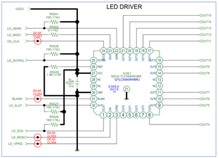
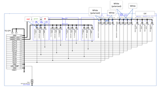
The circuit diagram is shown below.
There are two types of power supplies for the LEDs, as follows.
They are separated for each LED. The power supply is switched for each LED that emits light.
UNREG_LED1: White, white (polarized), UV
UNREG_LED2: Red, green, IR


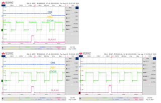
Below are the waveforms observed on a prototype board.
The relationship between GS_CLK and the BLANK signal is that a BLANK signal is inserted every 4096 GS_CLKs.
We were able to confirm that the phase of this GS_CLK and BLANK signal differs when the power is ON/OFF.

In Figure 21 of the datasheet, the phase relationship is as follows.
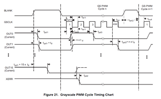
(Question)
Is there a possibility that a malfunction will occur if the timing "Tsu4" spec of 10ns or more is not met, or if the BLANK signal rises before 4096 times?
Are there any other reasons why this problem occurs?

Best regards,

  • Hi Customer,

    Our expert is currently out of office. He will reply to you later. Thanks for your understanding.

    Best Regards,

    Steven

  • Hello,
    How is the current status?
    I'm an FAE at an agency and I've been getting this question from my clients.
    We need your opinion on whether the malfunctions observed in customer evaluations could be caused by the phase relationship between the BLANK and GSCLK signals.
    Best regards,

  • Hi Kaji,

    Sorry for the late reply due to the sick leave before.

    For your problem, I'd like to ask a few questions about it.

    1. For your schematic, I'd like to know why there are some resistor between pin and pin, like R5501, R5526, R5527, R5528.

    2. For your capture waveform, I'd like to know why the BLANK signal toggled during the the high period of GSCLK on the first waveform.

    3. For your whole problem, I am not sure my understanding is totally correct. Do you have any report or contact information can share to me?

    BR, Jared

  • Thank you for your reply.
    The resistor in the circuit diagram is a pull-up resistor. Is there a problem?
    In the customer's ASIC circuit, GSCLK is input even during the period when BLANK=Hi.
    The BLANK does not switch during the high period of GSCLK by turning the power on/off.
    The customer thinks that it is no problem if GSCLK occurs during the BLANK period.
    However, if the falling edge of BLANK and the rising edge of GSCLK are in phase,this will violate the setup time standard and cause the LED to malfunction.
    When the falling edge of BLANK and the rising edge of GSCLK are in phase, is there a possibility that the LED connected to the output will malfunction?
    Best regards,

  • Hi Kaji,

    Do you mean that the pre-stage MCU doesn't have the pullup capability, so they connect a pull-up resistor?

    For your doubt, I think it's possible. Since based on the datasheet, the GSCLK and BLANK signal have the timing requirements.

    BR, Jared

  • Thank you for your reply.
    Your understanding about the pull-up resistor is correct.
    Does the timing requirement for the GSCLK and BLANK signals refer to TSU4 (min 10ns)?
    Will there be any problems with the OUT signal if the counter starts before being reset by the BLANK signal?
    Best regards,

  • Hi Kaji,

    Yes, as you understood, TSU4 is the timing requirement for the GSCLK and BLANK.

    As for is there any potential problem if the counter starts before being reset by the BLANK signal, I am not sure about that since we haven't never done this test for the disobeying datasheet.

    BR, Jared

  • Thank you for your reply.
    I had a meeting with the customer to review the situation.
    Because BLANK and GSCLK were not synchronized, the constraints of th4 and tsu4 could not be observed.
    So, we changed the circuit, observed the above constraints, and have been repeating the test. So far, no problems have occurred.
    However, my customer is concerned about whether this is really the right solution.
    Mass production is about to begin, so the problem needs to be resolved as soon as possible.
    So, I would like to know your opinion on whether or not a malfunction like this could occur if the constraints of th4 and tsu4 are not followed.
    Or is it possible to get the opinion of the designer of this product?
    Additional question: When BLANK is high, does GSCLK need to be low?
    By the way, the thread below is from one of my customers.
    The customer is not able to ask questions properly and has been contacting me repeatedly.
    This shows how anxious the customer is, so please cooperate with us.
    Best regards,

    e2e.ti.com/.../tlc5940-tlc5940rhbr

  • Hi Kaji,

    Good news, nice to hear you!

    As you can see in the datasheet, TLC5940 has been released 10 years and I never see the problem for the interface as long as you follow the timing requirements on datasheet. I think there should be no problem.

    For the additional question, I suggest to follow the datasheet to set the GSCLK to low when BLANK is high.

    BR, Jared

  • Thank you for your reply.
    I appreciate your quick response.
    There is something the customer would like to confirm just to be sure.
    >I suggest to follow the datasheet to set the GSCLK to low when BLANK is high.
    Is the above a specification that must be followed?
    What problems are expected if the above is not followed?
    Best regards,

  • Hi Kaji,

    First of all I want to clarify one thing, the role of the datasheet is to regulate the use of the customer, we can only guarantee that we write something in the datasheet, for some of the test conditions that don't match on the datasheet, To be honest, I'm not sure what's going to happen, and if you really want to know what's going to happen under this condition, you can email me, I then forward it to my boss and go to request the help of a digital verification engineer, as the bench test does not prove this condition effectively.

    Hope you can understand.

    BR, Jared