This thread has been locked.

If you have a related question, please click the "Ask a related question" button in the top right corner. The newly created question will be automatically linked to this question.

BQ25622: BQ25622RYKR+BQ27Z746YAHR+MSPM0C1104SRUKR Schematic scheme review

Part Number: BQ25622
Other Parts Discussed in Thread: BQ27Z746

Tool/software:

Dear Sir,

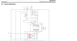
We have two projects with a customer and the projects use TI's guge ICs, charger ICs, MCU and LDOs. The customer requires us to get the approval from TI. Please see the schematicks and PCB layouts as the attached and please help to let us have your approval as soon as possible to have the projects moved on.

Thank you.1S4P PCB Layout 20240814.pdf1S2P PCB Layout 20240814.pdfSCH-PCB 20240814.pdf

  • Hello, 

    I will work to review TI charger IC portion of the designs and will provide feedback by early next week. I will then loop in the necessary expert to review the TI gauge portion of the design. 

    To get approval with fastest possible turnaround time I recommend you create another thread specifically asking for review of the TI MCU and LDO part numbers. 

    Best Regards,

    Garrett 

  • Hello, 

    Please see my comments below. 

    I have reviewed the BQ25622 portion of the schematic and all looks good. All necessary connections are made and required passive components are included. 

    Please ensure both layouts adhere to TI's layout guidelines listed in datasheet  section 11.  I will require .BRD files for the layout designs to review in greater detail. I have attempted to review using PDF files provided, but not all components and traces are identifiable.  

    Best Regards,

    Garrett 

  • Hello, 

    I have taken a look at the schematic you have provided, and is there a reason for using the C3 and C6 capacitors? Additionally, since you have ENAB pulled down to ground, the gauge will not be able to ever enter shutdown mode. If you wish to use the shutdown power mode, then you should not permanently pull down ENAB. 

    Regards, 

    Robert. 

  • Hello Robert, 
      The reason for C5 C6 is to refer to the schematic diagram of BQ27546. Is it OK to paste C5 C6 capacitor.      
    If SHIP mode is required, I will leave the ENAB foot unconnected (vacant), and I will only enter and wake up SHIP mode through instructions 0X0015 and 0x0016.  Is this OK?  Thank you
  • Hello Garrett1S2P Layout 20240814.brd1S2P Layout 20240814.PcbDoc1S4P Layout 20240814.PcbDoc1S4P Layout 20240814.brd,

    I have uploaded the attached files in two formats: pcb and brd, please help review again, thank you

  • Hi Putong, 

    Thank you for providing layout files. I can completed review of both designs and have the following comments below. 

    1S4P design:

    -Regarding SYS output capacitors I recommend moving 1 of either C17 or C19 near SYS pin rather than near the inductor pad. You already have a PGND plane near SYS node so it appears it would be simple enough to place one of those capacitors there instead. 

    -Regarding PMID capacitor placement, I recommend you look to further reduce the trace length from PGND back to BQ25622 GND pin. In the layout guidelines short copper trace from PMID caps to GND pin is important. 

    -Otherwise I see no obvious issues regarding the BQ25622 portion of the layout design. 

    1S2P design:

    -SYS output caps are recommended to be placed close to SYS pin. Ideally at least one would be closer SYS pin of BQ25622, but current placement near inductor pad is also understood.

    -Otherwise I see no obvious issues regarding the BQ25622 portion of the layout design. 

    Best Regards,

    Garrett 

  • Hello, 

    For the bq27z746 device I would recommend removing these capacitors as these are not recommended in the reference schematics for the BQ27z746.  Additionally, I would not leave ENAB floating. Instead it is recommended to connect ENAB to a GPIO to retain the full functionality. 

    Regards, 

    Robert. 

  • Hello Robert,

    There is no GPIO output PIN for this project, may I ask if I do not connect the ENAB (vacant), is there any problem? Or do you have any better suggestions?

  • Hi Putong, 

    Please be aware I have added an additional comment to my response above regarding the 1S4P layout design. You may want to consider shortening the trace length from PMID capacitors to GND pin of BQ25622. 

    Best Regards,

    Garrett 

  • Hello Putong, 

    I have seen people permanently pull down ENAB, but when you do this you forfeit the ability for the gauge to enter shutdown mode. This is why I suggested to connect ENAB to a GPIO for full functionality. I recommend referring to the enter and exit conditions for the power modes to see what functionality you would be loosing by permanently pulling ENAB down. 

    Regards, 

    Robert. 

  • Hello Robert

    I understand.  I change ENAB to not pull to GND, and I plan to change ENAB to not connect (empty).  Is there any problem with this?  (Because there is no extra GPIO PIN to connect) Thank you

  • Hello Putong, 

    It is not recommended to leave the ENAB pin floating. If you cannot connect the ENAB pin to a GPIO or a push button, then you can permanently pull this pin down, but you will lose the ability for the gauge to enter shutdown mode. 

    Regards, 

    Robert. 

  • Hello Garrett, the attached Layout has been updated as required, please help review again, thank you very much

    1S2P Layout 20240914.PcbDoc1S4P Layout 20240914.PcbDoc

  • Hi Putong, 

    I have reviewed the updated versions of both 1S2P and 1S4P layouts and I can confirm the suggestions from my earlier reply have been incorporated. 

    Therefore I see no obvious issues regarding the BQ25622 portion of either layout design. 

    Best Regards,

    Garrett