This thread has been locked.

If you have a related question, please click the "Ask a related question" button in the top right corner. The newly created question will be automatically linked to this question.

TPS3840: Reverse polarity protection

Part Number: TPS3840
Other Parts Discussed in Thread: TPS3760

Tool/software:

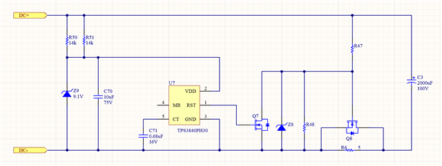
We are using the TPS3840 in a pre-charge circuit to control the charging of a large electrolytic capacitance on application of power. The TPS3840 reset output on power-up keeps a power resistor in-circuit to decrease the charging current; when the TPS3840 reset time expires, the precharge resistor is  bypassed. The capacitors are followed by a MIL-STD-1275 compliant filter with reverse polarity protection. In order to meet MIL-STD-1275, this pre-charge circuit must also meet the reverse-polarity requirements.

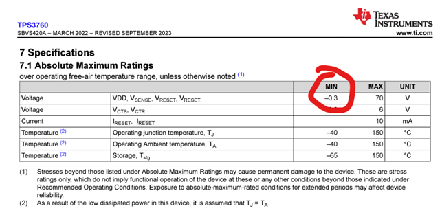
The VDD line for the TPS3840 is created from the main system input voltage using a zener diode regulator. If the power leads are reversed, the zener diode will clamp the voltage between GND and VDD to its forward drop; according to the datasheet, that voltage will vary from ~ -0.5V to -0.9V across the temperature range of -40C to 125C at a current of 5mA. However, the TPS3840 has an absolute minimum voltage of -0.3V. Will placing a reverse-biased Schottky diode in parallel with the zener provide sufficient protection? Is the zener sufficient on its own due to the current limiting resistors? Are there any other solutions you would propose to limit the reverse voltage in this situation?

Simplified schematic is shown below. Input voltage during the reverse polarity test will be -33VDC, meaning ~5mA will be drawn through Z9 and R50/51.

  • Hi Nick,

    Is the -33VDC coming from the DC- or is DC- GND and the reverse polarity happens on the DC+?

    Just looking at your bare application, I would recommend TPS3760, https://www.ti.com/product/TPS3760.

    The TPS3760 is a 65V device with a greater protection block than the TPS3840, which will help the device survive during the test.

    Jesse 

  • Hi Jesse,

    The referenced part has the same absolute minimum voltage noted on the datasheet and would have the same issue.

    The voltage is not a transient condition; it's a test meant to simulate a test mishap, where an operator hooks up the power line to our system backwards. In that case we need to draw little to no current and not be damaged. This is typically implemented by putting a pass FET in "backwards" such that the body diode blocks the wrong-way current, while current in the correct direction will flow through the body diode into a gate bias circuit that turns on the FET. We have that circuit in our downstream filter, but the TPS3840 circuit before that filter also needs to survive when the power leads are reversed.

    So specifically: normally, the DC+ input can be up to 33V higher than DC-. In the reverse polarity test case, DC+ is connected to +33V supply negative and DC- is connected to +33V supply positive. The 9.1V zener diode that is normally reverse biased will instead be forward biased, which will clamp VDD to roughly 0.5V to 0.9V below ground -- beyond the 0.3V spec, but current limited by R50/R51 to ~5mA. Normally reverse voltage can be tolerated on signal lines if it's current limited because of internal ESD clamping diodes, but I'm not sure if there's a similar beyond-datasheet tolerance for TPS3840 VDD.

  • Hi Nick,

    Sorry for the delay, I am looking into your inquiry more. I will update on Monday.

    Jesse 

  • Hi Nick,

    Yes the abs min rating of the TPS3760 is similar, but since the voltage rating of the TPS3760 is higher, incase of the zener diode failure will survive. 

    Also based on my testing of the TPS3760, with enough damping impedance on the sense pin, it is able to withstand more negative voltage before failure.

    Jesse 

  • Thanks Jesse. So since this is a standards-based test, looking for a bit more direct of an answer. So if I apply a reverse voltage to the VCC of the TPS3760 for the specified time (5 minutes), and that VCC is clamped by a zener diode forward voltage drop to be no lower than 0.9V below ground, then the TPS3760 will not be damaged? I'm asking because the response included "but since the voltage rating of the TPS3760 is higher", and I don't think the behavior under clamped reverse polarity has to do with the normal "forward" voltage rating.

    Note that the reverse polarity test of MIL-STD-1275 requires that the load NOT pull down the source voltage; I'm not sure how to connect the SENSE line in this condition. I can't connect SENSE to the normal +28V supply rail and protect it with a Schottky diode, because the Schottky diode would be forward biased under reverse polarity and would short the (reversed) supply lines.

  • Hello Nick - Our team will respond next week due to US holidays.

  • Hi Nick,

    Since it is a datasheet constraint, I cannot recommend any application outside of datasheet parameter.

    That being said, I have tested my TPS3760 on my EVM and exposed the VDD to -.900V for about 30mins. The TPS3760 was functioning normally afterwards. 

    Jesse