


Tool/software:
Hello we use the TPS7B7702QPWPRQ1 as 2 5V sensor supplies on our product. During an >28V overvoltage condition on either OUT1 or OUT2 the part fails. I am curious as to why because the data sheet says that it can handle up to 45V on the out pins.
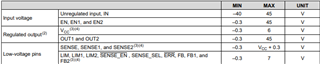
Our theory is that even though OUTx can go to 45 volts that the FBx will over voltage due to the voltage divider we use to get to 5V regulated output. The overvoltage on the FBx is 7V.
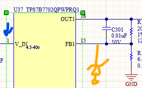
Do we need a zener diode or some clamp on the FBx pins to protect against this condition? This is what we believe we need (diode in orange)
We probed the pin 1 (blue arrow) when introducing a 28V conidtion on out 1 and this is a capture of that event. (pin 1 is fed by a 6.5V regulated supply)
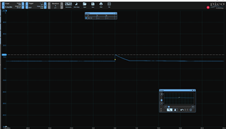
Pin 1 went from 6.5 to 12.1 volts then decayed for about 3ms. After this the chips out1 rail was held at 0-.1V.
Is our analysis correct and do we need a clamp on the FBx pins to protect against this?
