This thread has been locked.
If you have a related question, please click the "Ask a related question" button in the top right corner. The newly created question will be automatically linked to this question.
Tool/software:
Hi Team!
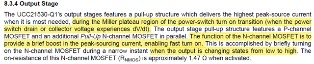
Could you please hep to explain how to understand this:
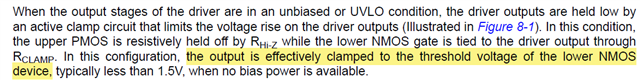
Another is about miller clamp:
How does this function realized?
Best Regards,
Josh Wei
Hi Josh,
1.) This is designed in the output stage of the gate driver. The P-channel MOSFET and the N-channel MOSFET in parallel for the high-side MOSFET design on the output stage allows this to happen. The NMOS allows for high current to flow through as compared to the higher internal resistance of the PMOS.
2.) This boosting from the NMOS is suitable for all types of MOSFET loads.
3.) The boost time duration depends on the MOSFET load turn on characteristics. This boost occurs during the Miller plateau region which varies among different FETs.
When UVLO is triggered, the low-side NMOS must be turned on and remain on. In this case, the output control block in the diagram Figure 8-1 on the datasheet outputs the threshold voltage of the NMOS to turn it on. I do not have details on the internal design of the output control block unfortunately.
Hope this helps.
Regards,
Hiroki