Tool/software:
Dear Texas Instruments Support Team,
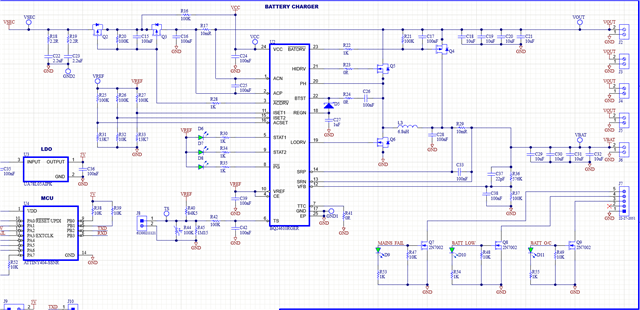
I am currently working with the BQ24610 IC for a battery charger application, and I have encountered an issue that I need assistance with.
Circuit Details:
- Power Supply: 20V DC applied to the input.
- Measurements:
- VOUT: 20V
- VBAT: 20V (nothing connected to VBAT yet)
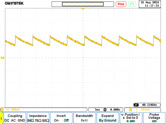
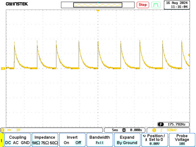
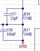
- VREF: Unstable voltage, observed as a ramp waveform between 200mV and 400mV.
- LED Indicators: Not functioning (no status indication).
Issue Summary:
Upon initial testing, I observed that the VREF pin was providing an unstable voltage. After further inspection, I discovered that I had incorrectly fitted a 100nF capacitor to the VREF pin instead of the recommended 1uF. Replacing the capacitor with the correct value improved the stability of the VREF waveform, but the voltage remains significantly lower than expected (around 300mV instead of 3.3V). Additionally, I am not seeing any output from the LED indicators.
Request for Assistance:
I would appreciate any guidance you can provide regarding potential causes for the VREF instability and the lack of LED indicator functionality. Are there any other parameters or configurations I should check to resolve this issue?
Thank you in advance for your support. I look forward to your insights.