This thread has been locked.

If you have a related question, please click the "Ask a related question" button in the top right corner. The newly created question will be automatically linked to this question.

MC33063A Evaluation

Other Parts Discussed in Thread: MC33063A, MC34063A

Requirement:

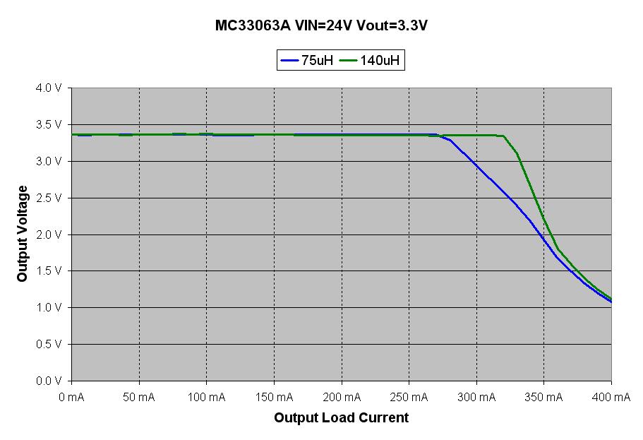
Input : 24VDC Regulated Output : 3.3VDC/0.2A

Regulator Used : MC33063A (SO-8 Package)

I'm facing below mentioned Problems:

1) Efficiency <40% (MC33063A temperature rise is very high)

2) Unable to load 0.2A on the 3.3VDC output (3.3V output drops)

3) In the above issue input power doesnt reduce when the output drops.

Previously I've used MC34063A for the requirement 24VDC input for an output of 5V/0.5A. I didnt face above issues here.

Please advice

Thanks,

John Mathew

  • Hello John,

    Both the MC33063A and MC34063A should perform the same. So it is odd that one worked and the other did not.
    The MC33063A should run cooler converting to 3.3V than to 5V, because the switch duty cycle will be lower.

    Do you use the same power components in your 5V and 3.3V designs?
    What values do you have CIn, Cout, Rcl, Inductor and diode?

    Do you have a scope capture of pin2?  This node holds a lot of information about how the buck regulator is performing.

    Regards,
    Ron Michallick

  • Hello Ron,

    Thanks for your reply.

    I did noy use same power components for both. Values used for 3.3V/200mA are as below

    Cin = 1000uF/50V, Cout = 470uF/16V, Rcl = 1R, Inductor = 100uH/0.6A, Timing Capacitor = 470pF, Diode = BAT54(SOT-23 Package)

    I've tried inductor values from 10uH till 1mH, and capacitor values 100pF, 470pF.

    Waveform captured at 2nd pin is attached. Input & output conditions are as below at the time of capturing.

    Consumption from input=0.08A from 24VDC. Output load is 0.1A for 3.6VDC. Output drops above 0.1A load.

    Regards,

    John

    Attachment : 4130.Test Waveform.pdf

  • Hello Ron,

    Thanks for your reply.

    I did not use same power components for both. Values used for 3.3V/200mA are as below

    Cin = 1000uF/50V, Cout = 470uF/16V, Rcl = 1R, Inductor = 100uH/0.6A, Timing Capacitor = 470pF, Diode = BAT54(SOT-23 Package)

    I've tried inductor values from 10uH till 1mH, and capacitor values 100pF, 470pF.

    Waveform captured at 2nd pin is attached. Input & output conditions are as below at the time of capturing.

    Consumption from input=0.08A from 24VDC. Output load is 0.1A for 3.6VDC. Output drops above 0.1A load.

    Regards,

    John

    Attachment : 4130.Test Waveform.pdf

  • John,

    The waveform looks good. The MC33063A should not get hot running like that.
    Does this happen on more than one unit? Perhaps it is damaged.

    Regards,
    Ron.


  • Hi Ron,

    I tried rigging up the whole circuit three times with new regulators (MC33063A) all the three times.

    Regards,

    John.

  • John,

    What is the inductor part number (data sheet link preferred)?
    I will test the cicuit this week and post the results.

    Ron.

  • Hello Ron,

    Inductor Part No : B82144A2104J000\

    Datasheet Link : http://www.datasheetarchive.com/B82144A2104J000-datasheet.html

    Thanks,

    John.

  • John,

    I built a test circuit using the MC33063A, but I did not have a 100uH inductor readily available so I recorded data with 75uH and 140uH. Attached is a load regulation chart.
    The MC33063A did not overheat. It felt  warm to a firm finger press at full load.  

    The main difference between my components and yours was my inductor had a closed loop core (1/2 inch outside diameter). I have not used a small RF chokes with the MC33063A before. However, I do not see why this would make a huge difference in MC33063A temperature.

    Can you measure the voltage on the Rcl resistor and CT pin voltage, there may be a clue to determine problem.

    Regards,
    Ron