This thread has been locked.

If you have a related question, please click the "Ask a related question" button in the top right corner. The newly created question will be automatically linked to this question.

BQ76952: The Alert pin cannot be cleared by the warp

Part Number: BQ76952
Other Parts Discussed in Thread: BQSTUDIO

Tool/software:

Dear TI Technical Experts,

I am encountering an issue with the ADSCAN function and ALERT pin on the bq76952 chip during my project development and would appreciate your assistance.

Problem Description:
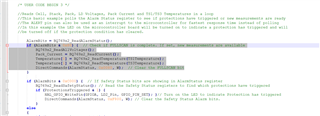
I have configured the ALERT pin for alarm functionality and enabled the ADSCAN feature. Upon completion of the measurement loop, the ADSCAN alarm is triggered, and the ALERT pin remains in the high state. According to the manual, I attempted to clear the alarm status by writing specific values to the 0x62 Alarm Status() register, specifically using a “1” to reset the needed alarm bits while keeping all other bits at “0”. However, writing 0x02 to 0x62 does not clear the ADSCAN alarm, and the ALERT pin continues to stay high.

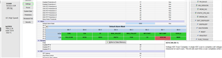
During my attempts to resolve this issue, I found that the ALERT pin only switches to low when all bits in the Default Alarm Mask are set to 0.

Additional Information:

  • My bq76952 is controlled by an hc32 microcontroller, with the MCU pins set for external interrupts.

  • I have double-checked the address and values written against the official example code, and they logically seem correct.

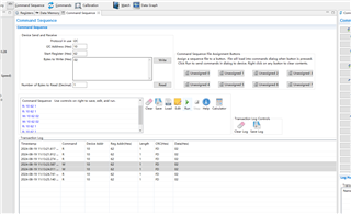
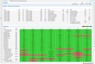
Attached is a screenshot of my current configuration in bqstudio, which might provide more clues.

 2024.08.19.gg.csv

Thank you for your time and assistance. I look forward to your response.

Best regards,

[Darluu]

  • Hello Darluu,

    The ADSCAN bit is set
    every time an ADC cycle is completed. This is a very quick process so after you clear the ALARM status, it could trigger again. What you are seeing is expected. If you want the ADSCAN bit to only trigger once, there is no other way of doing it other than disabling the ALARM for it after the first time.

    Best Regards,
    Alexis

  • Reply to Alexis_H:

    Thank you for your interest in the issue!

    I understand the configuration as you've mentioned: the ADSCAN should trigger every 252ms, and if cleared, it should pull high again after a maximum of 252ms. However, when I use an oscilloscope to monitor, I see no changes in any pin.

    I don't want the ADSCAN bit to trigger only once. My microcontroller detects a rising edge on the alert pin, reads the voltage, current, and temperature information, and then uses the code:

    c
    DirectCommands(AlarmStatus, 0x0020, W); // Clear the ADSCAN bit to make the alert pin go low

    After the measurement loop is completed, ADSCAN continues to trigger, the microcontroller reads the information and clears ADSCAN. This process repeats continuously.

    However, I'm having trouble as neither the microcontroller nor the oscilloscope can detect any changes in the level of the alert pin.

    I kindly ask you to try it out with my configuration on your end to see if the ADSCAN bit is correctly cleared and the alert has gone to a low level.

    Best Regards,
    Darluu

  • Hello Darluu,

    Thank you for clarifying. From the code you are sharing now, it looks like you are clearing the incorrect Alarm Status bit for ADSCAN.

    bqStudio will also tell you which Alarm Status is high. 

    Can you try changing that and seeing if that resolves your issue?

    Best Regards,
    Alexis

  • Hello Alexis_H,

    Oh, I'm very sorry, there was a typo in my previous messages. The command I actually used is: DirectCommands(AlarmStatus, 0x0002, 'W');. It's like this in my code, and I also use 0x0002 with the bqstudio software to clear it, as shown in the image:

    Best Regards,
    Darluu

  • Hello Darluu,

    Thank you for letting me know. I will review what you have shared again and get back to you. 

    Best Regards,
    Alexis

  • Hello Darluu,

    Thank you for your patience. After testing the command in the lab with your current configuration, I found no issues other than what you typed in the ‘Command Sequence’. You wrote it to the correct register, however, you need to write all the bits in. In Bytes to Write (Hex), you need to write ’02 00’, instead of just ‘02’.

    Best Regards,
    Alexis

  • Hello Alexis_H,

    Thank you for your reply. Do you mean that I need to write 02 00 (hex) in the 'Command Sequence' of the BQStudio software?

    However, could you explain why this is necessary? Because I observed that the Alarm Status value is 0x0002, and based on my understanding, I should write 0002. I'm very much looking forward to your explanation.

    Additionally, in my microcontroller code, if I want to clear the ADSCAN alarm using DirectCommands(AlarmStatus, value, 'W');, what should the value be?

    Best Regards,
    Darluu

  • Hello Darluu,

    Thank you for your reply. Do you mean that I need to write 02 00 (hex) in the 'Command Sequence' of the BQStudio software?

    That is correct.

    However, could you explain why this is necessary? Because I observed that the Alarm Status value is 0x0002, and based on my understanding, I should write 0002. I'm very much looking forward to your explanation.

    That is because the device stores values in little endian byte order. 

    Additionally, in my microcontroller code, if I want to clear the ADSCAN alarm using DirectCommands(AlarmStatus, value, 'W');, what should the value be?

    The value you had previously should be correct. DirectCommands(AlarmStatus, 0x0002, 'W');

  • Hello Alexis_H,

    This has solved my problem, thank you for your help!

    Best Regards,
    Darluu