Other Parts Discussed in Thread: LM5143, LM5148
Tool/software:
Hi,
I am simulating the LM5143A-Q1, configured for two-phase single output. Some of the relevant waveforms do not add up, although my output is somewhat close to my target. My application is 5V in, 1V out, and 10A out. I have attached the supporting analyses and design files. My findings are as follows:
- My target output is 1V/10A. I have the feedback network set appropriately, and I've tried a few variations of the resistor ratios, however I continue to measure 1.144V. This results in 11.44A output. No matter what I try, I cannot settle to 1V. It's very strange.
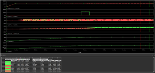
- As I approach steady state, PG1 is High for a brief time and then goes Low. PG2 is always Low. This behavior does not seem correct, particularly because of line item #3.
- Just around the time that PG1 transitions to Low, SW node 1 appears to stop switching while SW node 2 continues on. Looking at the following plot, this follows as SW node 2's inductor conducts, while the other SW node 1 inductor stops. Maybe I am misunderstanding the single output operation, but I would think both conduct equally.
The simulation is very slow, so I've saved a few of the trans files.
Any feedback with this circuit is greatly appreciated. Thank you.