Other Parts Discussed in Thread: TPS65987
Tool/software:
Hi Team,
My customer has BC1.2 detection and IC boot up queries as below. Could you please help to advise?
Thanks!
BC1.2 detection related:
1. What's the trigger condition of BC1.2 detection? Can it be trigger by SOC manually?
2. Does DP/DN pin on SOC needs to be Hi-Z mode when BC1.2 detection is occurred?
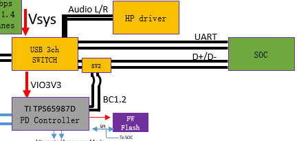
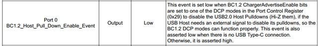
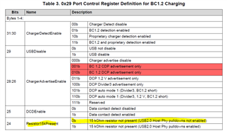
3. If SOC Hi-Z mode is needed but SOC not supported, can one of the TPS65987D GPIO be configed as USB switch control output to switch DP/DN out from SOC for BC1.2 detection? Will the below GPIO event ‘BC1.2_Host_Pull_Down_Enable_Event’achieve this function?

4. Does the DP/DN pull up and down during detection is controlled by TPS65987D, and no extra components is needed?
IC Boot up related:
1. For the external SPI FW flash, can we flash/update FW with test points that connected to others host(e.g. auto test station to flash FW on a new board)?
2. When plug-in adaptor with device in dead battery mode, inorder to only connect Vbus to PP_HV1(PP_HV2 keeps disconnected) can we use 'BP_ECWait_Internal ' boot config?

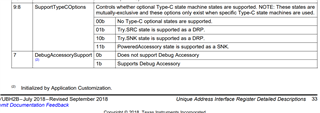
3.Can TPS65987D detect both CC with Rp pull-up Debug accessory mode?
4.How long does it take for TPS65987D to cool boot up and dead-battery boot up (with external SPI flash) before it can detect DAM? We are considering using its GPIO to switch USB line to UART for boot up log capturing, it may needs TPS65987D boot up faster than SOC.

Best regards,
Terry