This thread has been locked.

If you have a related question, please click the "Ask a related question" button in the top right corner. The newly created question will be automatically linked to this question.

TPS27S100: Two consecutive shorts, second one not recognized

Part Number: TPS27S100
Other Parts Discussed in Thread: TPS281C30, TPS281C100

Tool/software:

Hello

Is there some sort of minimum time between two consecutive short circuit events the TPS27S100 can recognize?

I have two very short short circuit events (~8µs) in my application, and for some reason the TPS27S100 only shuts down during the first one, but not the second one.

Here is an image of the short circuit events. Yellow is the output voltage of an H-bridge driven by the TPS27S100, cyan is my input voltage.

As you can see during the first short circuit the TPS27S100 switches the output off immediately as expected, therefor my input voltage does not drop at all.

During the second short circuit however the TPS27S100 does not switch off... Sadly I can't show measured currents with my scope at home, but I've used a current clamp yesterday in the office and the currents far exceed the set ILIM value of 0.5A. At one point I measured like ~8A or something...

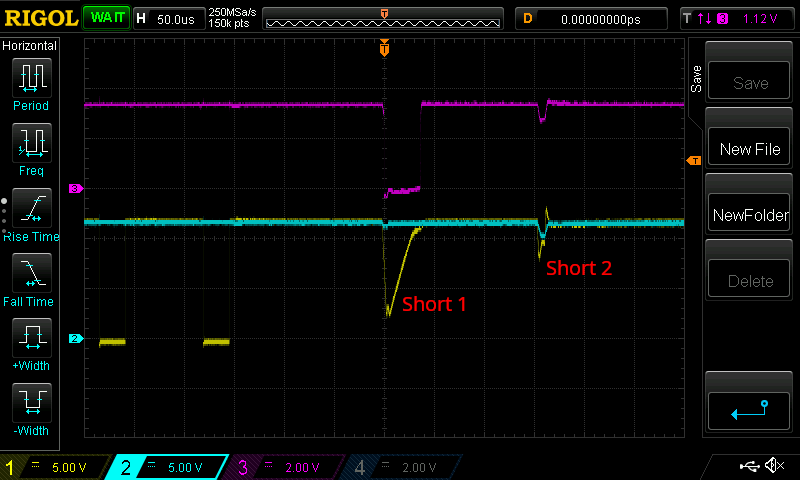
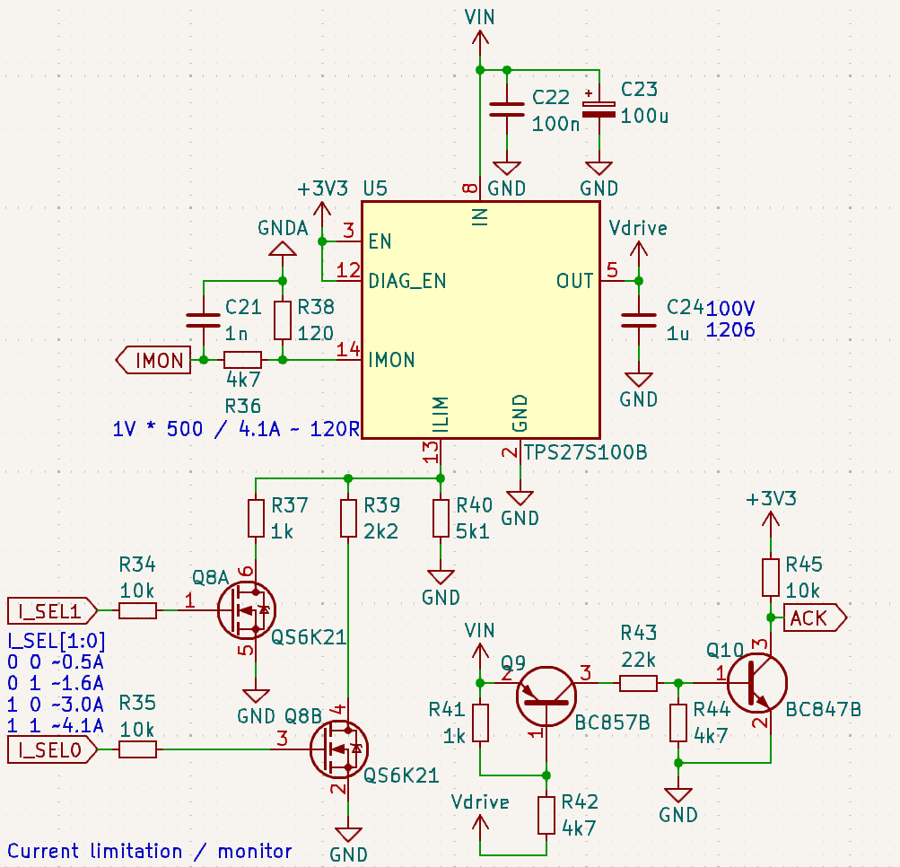
My application has the ILIM setting adjustable, but for that oscilloscope picture above I've used the 0.5A setting. The small transistor circuit below the TPS27S100 produces a digital signal whenever there is a large enough voltage drop between VIN and Vdrive. This voltage drop is what's causing the negative pulse of the magenta signal.

Oh and btw, the spice model does not show this behavior. When simulating my circuit everything worked fine...

  • I'm sorry for pushing this, but I really need an answer on this. Currently I'd have to assume that the TPS27S100 simply can't detect two shorts within 150µs because of some internal delay. If this is really true though, I absolutely must be mentioned in the datasheet.

  • Hi Vincent,

    I apologize for the delay on this. I have found similar, but nuanced and consistent behavior in the lab. Could you post waveforms with the current and we can proceed from there?

    And, if possible could you PWM the load at around 6.8kHz? I have found the load PWM frequency to affect this behavior.

    Thanks,

    Patrick

  • Hello Patrick


    Now I've got to apologize, I've been on holiday.

    I will see to it that I get hold of that current clamp sometime next week.

    Unfortunately modifying the "PWM" load frequency will not be possible though. The signal I'm applying to my device is basically UART with a specific baudrate. I can't just change the baudrate because then my device will not answer anymore.

    And yes, really, this short circuit here is a form of communication acknowledgement, sadly still very common in the model train business I'm working in ;)

    Best regards

    Vincent

  • Hello Patrick


    I've managed to get hold of our current clamp. It's the yellow channel, 10mA/1mV.

    The first peak is around 570mV, the second one 1110mV.

    Other channels are:

    Red - GND

    Blue - input signal (and supply)

    Green - internal trigger for the oscilloscope

    Best regards

    Vincent

  • Ok, I guess TI has no interest in further pursing this?

  • Hi Vincent,

    I'm very very sorry for the long delay on this! And model trains are great application!

    Tomorrow I will test if our next-generation device, TPS281C30 can detect these quickly repeated short-to-grounds. It unfortunately looks like TPS27S100 can't do this.

    I'll let you know the results of the test as soon as I finish it, and we can discuss the next steps from there.

    Again, sorry for the delay.

    Thanks,

    Patrick

  • Hello Patrick

    That was a close call. I was just about to order a new design that includes an additional comparator to get around the limitations of the TPS27S100. I'm eagerly awaiting your results with the new chip.

    Best regards

    Vincent

  • Hi Vincent,

    Glad we are able to find a more direct fix for this!

    Testing the TPS281C100 (next-generation of TPS27S100), the behavior looks as below (this was with ILIM = 0.5A):

    It looks like the short circuit when the output is (partially) on results in a very short spike about 2.5-3A (this is not unexpected, as the short-to-ground was through a very short/low impedance cable), then when the part reenables into the short, the current is limited to 0.5A properly. In both cases, the part correctly detects the short-to-ground.

    If the shorts in your application are weaker/have a bit more inductance and resistance, then the current peak won't occur and the part won't shut off before reenabling - it will just start limiting current to 0.5A.

    Does this look like something that can work in your application, instead of the TPS27S100?

    Thanks very much for your patience on this.

    Thanks,

    Patrick

  • Hello Patrick


    Thanks for the fast reply.

    I have problems interpreting the oscilloscope recording though.

    Any chance you've swapped the labels of VIN and VOUT?

    It looks like you maintain the short circuit the whole time starting from t=200µs?

    In my application the short circuits are really only ~8µs long and may occur either

    • Once after some data transmission
    • Twice after some data transmission with 200-5000µs between them

    The shorts are always low impedance as they are created by an H-bridge, so basically just RDSon and maybe some small shunt resistor. What I'd really need is a reliable voltage drop between VIN and VOUT each time. So the device would therefore have to be able to switch off the output at the first short circuit, then switch it back on within less than 200µs, and switch it off again if a short circuit occurs again. Only then would I be able to replace my current TPS27S100 + comparator design with the TPS281C100.

    Best regards
    Vincent

  • Hi Vincent,

    Sorry about that, in the rush I forgot to turn off the waveform labels and manually label on my response.

    Yes, dark blue is VOUT, light blue is VIN, magenta is unused, and green is IOUT.

    The load applied was a PWM'd MOSFET (<5mOhm on resistance), 10kHz switching frequency, 70% duty cycle. The same behavior happened at duty cycles, and at 6kHz at all duty cycles.

    When there is a short to ground, the device every time enforces the full voltage over it, unlike what we see in TPS27S100.

    Thanks,

    Patrick

  • Hi Vincent,

    I tested a bit more with your above conditions:

    -Labels are correct (magenta is TPS281C100 FAULT pin)

    -Burst of 2 8us signals at 6kHz (~160us apart)

    -Load is the same, <5mOhm MOSFET PWM'd at the above condition

    -RILIM is set to 0.5A (the pulse is not long enough for the device to start regulating current)

    -The turn-on slew rate is fixed, and can't be changed - however, VOUT rises to about 85% of VIN in the ~160us between the shorts

    The FAULT pin doesn't always go low on the second pulse, but nevertheless VOUT always reliably drops.

    Does this part look like it will work?

    Thanks,

    Patrick

  • I think that will do, thanks for taking the time!

  • One last question, when will the TPS281C100 be available in HTSSOP?