This thread has been locked.

If you have a related question, please click the "Ask a related question" button in the top right corner. The newly created question will be automatically linked to this question.

TUSB1046EVM: No video output from dev board

Part Number: TUSB1046EVM

Tool/software:

Hello, 

I purchased a TUSB1046EVM, I received revision F of the board.  I connected the DP input, external 5V power and on the other end the Type C port to a Type C monitor.  It did not work.  So I tried two more different type C monitors (different brands as well) that are known good and confirmed to work with iPhone/Samsung phones.  However through the dev board I get no signal out.  The monitors simply flicker on and off.

I tried to download the user guide but they are all for the older revisions of the dev board and the jumpers and connector names have changed compared to the older version board.  So what do I need to do to get a video out of this dev board (revision F)?


Thanks.

  • Hi,

    Thanks for reaching out. Can you send an image of the board you're using with Jumper settings shown?

    I'll take this board in to the lab and test it myself. Once I confirm video data passes correctly, I can show you the setting I used. Let me follow up tomorrow with an update on this.

    Best,

    Shane

  • Hello, here is the photo:

  • Hi,

    I tested this board today and was able to pass video successfully. Here are the board settings I used:

    I had to drive HPD high using a jumper wire on JMP9. Please check that HPD is around 3.3V when plugging in your video sink.

    Here is the setup I made. Video passes from the PC, through the 1046 EVM, and to the monitor through the Type-C port.

    You need to drive HPD using a jumper wire, or the TUSB1046 will not pass video data. Please refer to the board image to see which jumper needs to be driven high. Can you try your test with HPD driven high and the board settings I used?

    I tried to download the user guide but they are all for the older revisions of the dev board and the jumpers and connector names have changed compared to the older version board.

    You're correct that the schematic in the user's guide on TI.com is outdated. Let me provide the correct schematic here: 1004.TUSB1046 EVM Schematic Rev F.pdf

    Best,

    Shane

  • Hello, I tried the jumper wire and also adjusted the jumpers per your photo but I still just see flickering on the display. Please review my photo just in case.  I have tried both the USB and DC 5V inputs.

  • Hi,

    Can you describe your setup? The DisplayPort connector should be plugged into your DP source, while the USB-C port should connect to the monitor/sink.

    Can you confirm the cables you use work independently of our EVM? (direct dp source to sink test). I've seen a similar question in this E2E thread. Can you take the debug steps in that thread and see if it fixes the issue?

    Best,

    Shane

  • Hi, 

    I have tested all other components in the setup and confirmed they work.  I have also tried multiple cables, computers, different brand monitors and different brand computers.  I also tried a PCIe video card because I saw in the other post someone had success doing that.  But in all cases my display just flickers with no video.  Windows does not detect a secondary display as well.

    I am connecting the Dev board to a generic PC (I have tried Asus and Lenovo) and connect the USB power input through the Type B connector of the dev board, and the display port output from the PC to the dev board.  I have also tried using an external 5V DC power supply.  From the USB type C output I connect a thunderbolt 3 cable from there to a Viewsonic monitor using a type C to DP adapter cable.  I have also tried to connect to a native type C monitor as well.  If I remove the dev board and put a Samsung phone/iPhone/PC with type C DP alternate mode and connect tot he monitors they all work.

    If you would like a video of anything or a video call, I wouldn't mind.  Please let me know.

  • Hi,

    The settings on your board look ok, so its strange that video won't pass through the EVM. Are you able to see the monitor show up on your PC when the connection is completed? 

    As long as HPD is at 3.3V, you should at least see a monitor detected on the PC. Can you confirm whether this shows up?

    I'll be on travel until Thursday of next week. I can certainly support a call after that point. Typically the debug process for video over type-C will be to:

    1. Check that the HPD signal is passing correctly. If you see a screen detected on the PC, then HPD is working and you can move to step 2.

    2. Check that the AUXp/n common mode voltages are correct, and AUX signaling is passing through. AUX is working if you are able to see screen information (resolution, manufacturer, etc.) show up on your PC when the screen is plugged through the EVM. Once this is confirmed, move to step 3.

    3. Check that the EQ settings are correct (DPEQ jumpers). Over or under-equalizing the signal could cause video to fail passing through. You can adjust the EQ settings until the signal works.

    4. If it still does not work after step 3, try flipping the type-C cable a few times and changing the order of plugging in the DP cable and USB-C cable. I've had cases where plugging the type-C and DP cables in a few times gets video to pass through, though it should not be too difficult.

    Best,

    Shane

  • Hi Sir,

    Just to clarify, can you check whether R36 or R37 is installed on your board? These should be located on the bottom of the board and, if I'm not mistaken, share a resistor PAD near JMP9.

    I ask because R36 should be populated if you're using GPIO mode. That is the way my board is configured, but I realize this may not be the case for your board.

    Best,

    Shane

  • Hi, 

    I just confirmed R36 is populated and R37 is open.

    Not sure if this is normal but my board has a jumper wire on it from C15 to C18... this is how it came from brand new.

    The PC's I've tested doesn't detect a secondary display.

    Thanks,

    Jae

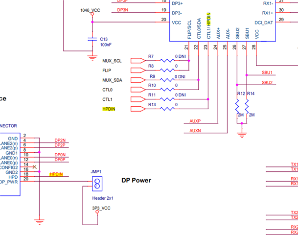
  • What voltage do you see on R13 when a display is plugged in to the type-C port?

    This should be at 3.3V with the display connected. I ask because this is the HPD signal that goes upstream to the PC. When the PC detects this HPD signal, it should show a display, even if video does not pass.

    Best,

    Shane

  • R13 shows 0V regardless if a type C monitor is plugged in or not. But HPDIN on JMP9 shows 3.271V.

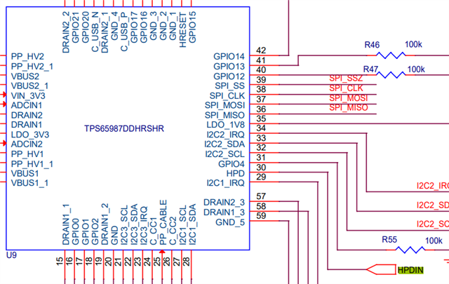
  • This is interesting. The PD controller should be driving this signal high when a monitor is plugged in to the type-C port. Perhaps something is preventing this.

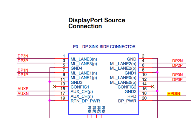
    For context, HPDIN on JMP9 will connect to the HPD of our device (TUSB1046). Its good that this is being driven high, but due to the board design this HPD is separate from the HPD signal that goes upstream to the PC. In order for the board to work in GPIO mode, both of these need to be high. This would ensure both our device and the PC can detect that a display is connected.

    The upstream HPD signal is directly connected to the PD controller's HPD output. When a display is connected via the Type-C port, the PD controller should drive this high:

    Applying an external pullup to 3.3V on this net may get the PC to recognize the display correctly. I can try and test this when I'm back in the lab later this week.

    Best,

    Shane

  • Thank you, looking forward to your feedback!

  • Will keep you updated when I test.

    Best,

    Shane

  • Hi,

    For the DP only testing, can you please try the following steps?

    1. R7, R9, R13 un-populated

    2. R8, R10, R11, R12, R14 populated

    3. R36 and R37 should both be populated then you don't need the external jumper wire as the HPD from the PD controller will drive TUSB1046 HDP/DCI_CLK

    4. Leave USB unconnected on P1

    5. Have external 5V provided on J5

    6. DP cable connected to P3

    7. Type-C cable connected to P2 

    8. Use a multi-meter check the voltage on the middle pin of J1. J2, and J3. You should see J1 and J2 both at 3.3V, and J3 either 0V or 3.3V. 

    9. If you flip the Type-C cable, then you should see the middle pin of the J3 change from 3.3V to 0V, or from 0V to 3.3V. This confirmed the PD controller is working

    10. Check pin 1 of JMP9, it should be 3.3V, indicating PD controller driving the HPD high

    11. You should see the Type-C display at least being recognized

    If you don't see the display working, then I would like to swap the EVM with you and see if it solves your issue.

    Thanks

    David

  • Hi, 

    I removed the jumper wire Shane suggested to drive HPD.

    I have tried your suggestion 1-7.  

    I measured J1=0V, J2=3.3V, J3=3.3V.

    I flipped the type C cable and J3=3.3V and didn't change.

    I checked pin 1 of JMP9 and it was 0V.

    The type C display is not being recognized in Windows on the computer.

  • Hi,

    I flipped the type C cable and J3=3.3V and didn't change.

    This suggests that the PD controller is not working correctly. What current can the external power jack supply to the board? I want to be sure the board is getting enough power here. Anything around 1A - 1.5A ought to be enough.

    Do you have a totalphase aardvark or similar SPI adapter to flash firmware to the PD controller? If you do, I can provide a firmware file to flash that would check whether the PD controller firmware is configured correctly.

    I am back in-office and was able to test this board. In my case, the FLIP signal (J3) toggles between 0V and 3.3V as it should.

    Best,

    Shane

  • Hi, 

    The external power can support 5V @ 4A.  The behavior is the same using the USB 3.0 power input.

    I do not have a SPI adapter unfortunately, can I send this in for RMA?

    Thanks.

  • Hi,

    Absolutely. Please use the resources found on TI's customer support center.

    If there's anything else I can help you with, let me know.

    Best,

    Shane