This thread has been locked.

If you have a related question, please click the "Ask a related question" button in the top right corner. The newly created question will be automatically linked to this question.

TPSM64406: TPSM64406 question

Part Number: TPSM64406

Tool/software:

Hello team,

My customer has some questions. Would you please advise?

1. The customer would like to use TPSM64406 as the following condition. Is it possible to use the following condition?
     Vin = 14V
     Vout = 2.5V
     Iout = 6A,  single out primary mode
     Fsw = 0.9MHz - 1.4MHz of external clock

2. When it is single out primary mode, how should we set MODE/PG1 pin?  Is the floating OK or 100kohm pullup to Vcc? 

3. When the output voltage is 2.5V, what do you recommend switching frequency?
    The customer hope 0.9MHz - 1.4MHz, but as far as I saw Table 7-4 in the datasheet,  all frequency is not possible. What is the maximum switching frequency?

4. When the customer do not use external clock, they want to use TPSM64406 as FPWM mode e.g. when TPSM64406 power up. Is it possible to use 1kohms pullup resister at SYNC pin?

5. When the external clock applies to SYNC pin, do we need AC cupping such as 1nF capacitor, or DC cupping is OK?

6.  How should we set soft start using Capacitor  at SS pin of single out primary mode? Would you please share the equation?

7.  How should we set PG1 and SYNC_OUT pins in single out primary mode although the customer do not use them?  Is the floating OK?

8. The customer is considering the following dual output mode. Is it possible?  I think that the external frequency is too high for Vout 1V or 0.95V. Is it correct?
  
Consdition1
    VIN = 5V
    Vout1 = 0.95V @ 3A
    Vout2 = 1.8V @ 3A
    External clock : 0.9MHz - 1.4MHz

Consdition2
    VIN = 5V
    Vout1 = 1.0V @ 3A
    Vout2 = 2.0V @ 3A
    External clock : 0.9MHz - 1.4MHz

Your advice is appreciated.

Best Regards.
Akihisa Tamazaki

  • Hi Akihisa,

    I have reviewed your questions and will answer them below:

    1. Yes. However, for 6 A out, two devices will need to be used in a multi-phase interleaved fashion such as in figure 7-4 of the datasheet.

    2. In single output primary mode, this pin is a PG1 pin and cannot float and must be connected to a suitable supply. VCC works.

    3. The maximum switching frequency of this device is 2200 kHz. For a 2.5 VOUT, you could use 0.9 MHz, but keep in mind that you might run into ton min issues which are found in the EC table of the datasheet.

    4. I do not believe a pull-up resistor is recommended on SYNC.

    5. AC coupling is not required for sync and the clock can be directly connected to SYNC. Please see section 7.3.9 of the datasheet for more details.

    6. You can find this equation in the design calculator. It seems to be Soft-start time = Soft-start cap * 40,000

    7. For PG1 please see point 2 above. For SYNC_OUT, this can be left floating if not used. However, if the interleaved stackable operation is desired, this must be tied to the MODE pin of the second device.

    8. For validation of these conditions, please utilize the design calculator.

    Thank you,

    Joshua Austria

  • Joshua-san,

    Thank you for your advice.

    1. Yes. However, for 6 A out, two devices will need to be used in a multi-phase interleaved fashion such as in figure 7-4 of the datasheet.

    1) I could not find in the datasheet why two devices will need.  out1=3A and out2=3A for 6A output should not be available?

    2) The customer should use external synchronization of 1MHz. There is recommendation Table 7-4 in the datasheet. Can we consider to use TPSM64406 if  there are no issue when we utilize the design calculator?

    Best Regards,
    Akihisa Tamazaki

  • Hi Akihisa,

    1. Sorry yes, you are correct. I misread the specification. 6A is available on one device.

    2. Yes, utilizing the calculator is a good place to begin your application. If you see no issues there, TI always recommends bench testing in addition to validate your desired aspects from your design.

    Thank you,

    Joshua Austria

  • Joshua-san,

    Thank you very much for your comment.

    If the customer has additional questions , let me ask you in this thread.

    Best Regards,
    Akihisa Tamazaki 

  • Hi Akihisa,

    You're welcome. 

    Joshua Austria

  • Hello Joshua-san,

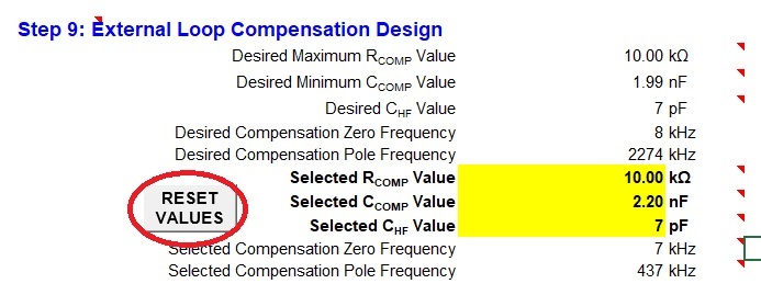
    I am using  the design calculator. When I clicked the reset value for COMP value, the error message was shown. It seems that there are no file to calculate.
       

    error massage : "LM(Q)66480_A0_A2_Quickstart _Tool _REVA.xlsm" is not found as below.


    Would you please advise me to fix?  If you share the new version design calculator, it would be helpful.

    As another way, the datasheet describes the following value is used as initial value.  Is it okay to delete CHF value to apply the following value?
    Rcomp = 11kohm, Ccomp = 2.2nF,  CHF = not used

    Your advice is appreciated.

    Best Regards,
    Akihisa Tamazaki

  • Hi Akihisa, 

    Apologies, I may have sent the incorrect link, the one you seem to have is the LMQ66480 one. Please see this one here: https://www.ti.com/tool/download/TPSM6440X-DESIGN-CALC Please make sure that you have macros enabled for the calculator. 

    Additionally, yes, you can change the values in the table and see how that affects your bode plot.

    I am not sure about the CHF value. I would stick to what is given by the datasheet if it matches your application as a first step. If you have an application that does not match any datasheet example, then I would begin utilizing the calculator to help validate your solution. In any case, TI recommends validating your solution on the bench as well apart from the calculator to ensure that your solution is sound. The calculator is meant to give you a good idea of what is recommended and will likely work when using our part as we have tested it.

    Thank you,

    Joshua Austria

  • Joshua-san,

    Apologies, I may have sent the incorrect link, the one you seem to have is the LMQ66480 one. Please see this one here: https://www.ti.com/tool/download/TPSM6440X-DESIGN-CALC Please make sure that you have macros enabled for the calculator. 

    Although I downloaded and tried again, the situation was not changed.  The software tried to access to a0496455 PC, but did not work. I think that a0496455 PC is not power on.
    If it is possible to fix this cocurator issue, I am glad for all users.

    I am not sure about the CHF value. I would stick to what is given by the datasheet if it matches your application as a first step. If you have an application that does not match any datasheet example, then I would begin utilizing the calculator to help validate your solution. In any case, TI recommends validating your solution on the bench as well apart from the calculator to ensure that your solution is sound. The calculator is meant to give you a good idea of what is recommended and will likely work when using our part as we have tested it.

    I understood. I asked the customer to do what you suggested.

    Best Regards,
    Akihisa Tamazaki

  • Hi Akihisa,

    Can you please send me the file you were attempting to open?

    I can try and look internally and see if there is a fix, but I need to see the file to understand the error better.

    Thank you,

    Joshua Austria

  • Hi Akihisa,

    Yes I see the error now. I will reach out to the responsible engineer and look for a fix. In the meantime, I would suggest that you manually change Rcomp, Ccomp, and CHF to validate your solution as this may take some time.

    I will close this thread for now, but please feel free to open the thread again to ask any questions down the line

    Thank you,

    Joshua Austria