


Tool/software:
I'm designing a card that needs a DC-DC conversion from 24V to 5V with for a high load (IOutMin = 2A) and low EMI levels, so I choose this converter.
I'm now designing the power stage. This circuit has not any AC entrance. The input port of the converter has 2 lines incomming from a DC source supply (24V): no diode rectifier between pwr input connector and the converter.
The card will have not many digital circuits: One microcontroller (expressif ESP32C3mini) for addressable LEDs strip control. LED strip will be connected to this board using a PCB connector for wires.
This card hasn't safety ground. No earth connection.
I used the design tool and the circuit has been something like this:
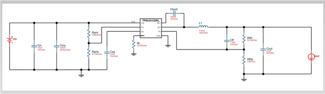
fsw = 1.8Mhz
Vin = 24V
Vout = 5V
Iout = 2.5A
Although the aparently simplicity, this card should pass EMI conducted tests.
I read the datasheet, and technical documents related to this buck converter and texas instruments buck converters in general looking for informartion about input filtering suggestions.
App notes:
This documentation is saying that buck converters hasn't common mode noise, due they haven't a third line for safety ground. Only differential mode filtering input is needed. This mentioned paper explains how to design a Pi filter for your buck converter.
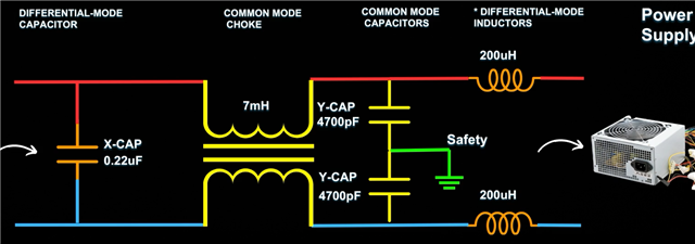
I'm very confused because other bibliography I read, says that any parasitic C or L between a conductor (such as a wire) and a real earth proximity can cause great common mode EMIs at the two lines (Vin+ and Vin-) entering to the input port of the converter. So an common mode EMI filter would also be needed:
Other example on how to combine common mode filter with diff mode filter:
The fact is that Texas Instruments tools for automatically calculate values and place components has not offering common mode filtering circuit at the input, it only does with diff mode filter. No documents talking about using common mode filters, etc..
- Is it true? will it never get common mode noise? Can I really forget EMI common mode filtering for passing class A conducted tests? Can I avoid it and can I only put the differential mode filter in Pi?
- If answer to question number 1 is true: another questions is that most of the Pi online calculator ask for the Zo value of the output Pi filter. But I need the Zin of the input port of the converter to adjust Zo of the filter I want to put, but how can I calculate this?
PD: card size form is important, to save space in this stage is needed.
Can anyone help me designing the input filter correctly?
