This thread has been locked.

If you have a related question, please click the "Ask a related question" button in the top right corner. The newly created question will be automatically linked to this question.

BQ25758: BQ25758 Reverse Mode

Part Number: BQ25758
Other Parts Discussed in Thread: TPS25751, , TPS25751EVM, BQ25756, BQ25798, BQ25713, BQ25790, BQ25792, BQ25731, BQ25756EVM

Tool/software:

How does the BQ26758 get set into reverse mode?

Presetting of registers? What method?

Info from TPS25751? What settings?

  • Hello,

    The BQ25758 gets put into reverse mode when the register EN_REV gets set to 1. You'll need to communicate with the BQ25758 over I2C to set EN_REV=1.

    Let me know if that answers your questions.

    Best Regards,
    Ethan Galloway

  • Hi Ethan,

    Will the TPS25751 set this register in a configuration similar to Section 4.2 of slvucp9a EVM User's Guide: TPS25751EVM
    TPS25751 Evaluation Module, exceptions being BQ25758 instead of BQ25756 and 45W power supply instead of a battery.

    Or would the EN_REV need to be set by a another I2C source i.e microcontroller?

    Thanks,

    Rick

  • Hi Ethan,

    There seems to be a disagreement between the BQ25758 Datasheet for REG0x19_Power_Path_and_Reverse_Mode_Control Register Field Descriptions and the Battery Management Studio (BMS) definition for that same Register.

    It seems that BMS allows bit 1 to be set as EN_AUTO_REV; this is not discussed in the Datasheet.

    I assume that setting this bit will allow the BQ25758 to enter Reverse mode on power up?

    Please verify this

    Thanks,

    Rick

  • Hello Rick,

    The TPS25751 does not support the BQ25758. You'll need to use an MCU to communicate with I2C to the BQ25758. The MCU will have to handle interpreting the USB signals and writing the commands to the BQ25758.

    The EN_AUTO_REV bit should not be there in the BMS file. We'll work on removing that.

    Let me know if you have any other questions.

    Best Regards,
    Ethan Galloway

  • Hello Ethan,

    From what I can gather, in order to implement a DRP USB-PD PPS with the TPS25751 and any of the following:

    BQ25790, BQ25792, BQ25798, BQ25713, BQ25756, BQ25758

    an external microcontroller is required to query the 751 PDO Contract and setup the BQ257xx in reverse/OTG mode

    Let me know what I am missing

    Thanks,

    Rick

  • Hello Rick,

    The TPS25751 doesn't have firmware to communicate with the BQ25758. I recommend using an external MCU to set the contracts.

    The TPS25751 will work with the BQ25756, BQ25759X, BQ25731, and BQ25713.

    I've also attached some example code for an MCU driver for the BQ25756. The registers are very similar to the BQ25758:FREERTOS_V1.3.7z

    By the way, can you tell me why you reverse mode on the BQ25758?

    Let me know if you have any other questions.

    Best Regards,
    Ethan Galloway

  • Hello Ethan,

    The application I am developing has the following characteristics:

    1) Supply USB-PD charging power (+5, +9, +3.3-15PPS) to Samsung Tab S7/8/9 -UFP

    2) No need for battery charging

    3) Supplied with 45-60W DC

    4) DRP Power

    5) DRP Data - USC-C 3.x HUB

    While the TPS25751 will work with the BQ25756, BQ25759X, BQ25731, and BQ25713 to set them up as battery chargers, it does not seem to set them up to supply Reverse or OTG voltages without a microcontroller to interface with both the TPS25751 and the BQ257XX I2C to achieve the required supply voltages upstream.

    Comments?

    Thanks,

    Rick

  • Hello Rick,

    Thanks for being patient with this. I will get back to you on this setup.

    Best Regards,
    Ethan Galloway

  • Hi Rick,

    I am an engineer who supports the TP25751 family of devices.

    While the TPS25751 will work with the BQ25756, BQ25759X, BQ25731, and BQ25713 to set them up as battery chargers, it does not seem to set them up to supply Reverse or OTG voltages without a microcontroller to interface with both the TPS25751 and the BQ257XX I2C to achieve the required supply voltages upstream.

    When you say Reverse/OTG, are you referring to USB-C Sourcing?

    The PD controller will communicate the the mentioned BQ devices to output the correct source voltage when it is requested by a PD sink. We do not currently have support for the BQ25758, so using that part would require MCU control.

    The 751 supports:

    USB-C PD sourcing at 5V, 9V, and PPS with compatible TI BQ Chargers

    DRP Power

    DRP Data

    Thanks and Regards,

    Chris

  • Hi Chris,

    When you say Reverse/OTG, are you referring to USB-C Sourcing?

    I would say YES but that is not the terms used in the datasheets.

    I have a 25751EVM and 25756EVM and have connected them IAW the 25751EVM SLVUCP9A Section 4.

    I have connected bench power supply 9VDC to 25756EVM J3 Vout.

    I have configured the 25751EVM with this JSOM

    https://www.dropbox.com/scl/fi/q9kglz375i0b8hoa4g4xy/751-756-config-9-4-24.json?rlkey=8cknqhjdce3rkku7yxuhd6q1z&dl=0

    I have connected to AVHzY CT3 to test connection.

    The setup does not provide PPS. It tries to switch but no power in the PPS requested mode and the CT3 reboots.

    In this configuration will the 25751 command the 25756 to enter Reverse mode/USB-C sourcing of PPS voltage to the 25751EVM PPHV?

    Comments?

    Regards,

    Rick

  • Hi Rick,

    When the TPS25751 enters a source mode, it should send an I2C command to the BQ25756 to enable reverse mode. PPS source requires constant updates of the output voltage, so there should be multiple writes on I2C to the BQ device to configure the output voltage during PPS.

    Can you measure and report the I2C transactions on the I2Cc lines of the TPS25751? The traffic will verify if things are being programmed properly.

    Thanks and Regards,

    Chris

  • Hi Chris,

    When the AVHzY CT3 Triggers Fast Charge the following parameters are received:

    Power Delivery 3.0

    Available PDOs:

    (1) Fix                 5.00V @ 3.00A

    (2) PPS                5.0 - 20.0 V  @ 2.2 A

    When the AVHzY CT3 Requests PPS the following I2C messaging occurs

    6B 19 20                             EN PFM

    6B 19 20                             EN PFM

    6B 17 C8                             Charger Control

    6B 0C 00 00                        Set Reverse Mode Voltage Limit

    6B 0A 00 00                        Set Reverse Mode Current Limit

    6B 19 21                               Enable Reverse Mode

    The Vusb drops from 5V to 0V, the CT3 resets and the Vusb rises to 5V

    Thoughts?

    Rick

  • Hi Rick,

    For PPS, the I2C messages are expected, but there do seem to be some missing. On startup/config, we do send some "safe" I2C messages to configure the BQ device, so setting the reverse voltage and current to 0 is not unexpected. 

    It is not expected that the PD controller requests 0 volts after a contract is requested though.

    We do expect the PD controller to eventually program non-zero values for the voltage and current during run time.

    I'll need a couple days to setup an test bench and test your json in the lab.

    Thanks and Regards,

    Chris

  • Hi Chris,

    Any luck in testing this setup?

    Regards,

    Rick

  • Hi Rick,

    I am still looking into this. I will keep you updated.

    Thanks and Regards,

    Chris

  • Hi Rick,

    Thanks for your patience.

    I tested your json with the TPS25751EVM and BQ25756 EVM and had no issues using PPS. We also have an AVHzy CT-3, and I am seeing no issue with PPS at no load.

    I'm thinking it may be a setup issue.

    Please verify the following:

    • EEPROM was flashed properly from the GUI
      • When the JSON is loaded to the GUI and Flash to Device is used with the EVM, does it complete successfully?
    • Power cycle the board after the new image is loaded so the PD controller can reboot
    • J1 jumper on the TPS25751 EVM is in the 'lower' position. The bottom and middle pins should be connected.
    • Rainbow 2x4 jumper is connected properly between boards
    • power connector is connected between boards
    • What voltage are you applying at J3 of the BQ25756EVM?
      • Confirm the PD controller is powered by checking the PP5V, VIN3V3 and LDO3V3 voltages
      • Make sure I2C is acking when sent from 
    • Can you negotiate a 5-V fixed contract?

    Are you familiar with the Saleae logic analyzer? I can share the Saleae logs of the setup working if needed.

    Thanks and Regards,

    Chris

  • Hi Chris,

    Thanks for your patience.

    Please verify the following:

    • EEPROM was flashed properly from the GUI -YES
      • When the JSON is loaded to the GUI and Flash to Device is used with the EVM, does it complete successfully? YES
    • Power cycle the board after the new image is loaded so the PD controller can reboot   Done
    • J1 jumper on the TPS25751 EVM is in the 'lower' position. The bottom and middle pins should be connected. YES
    • Rainbow 2x4 jumper is connected properly between boards YES
    • power connector is connected between boards YES
    • What voltage are you applying at J3 of the BQ25756EVM? 9VDC from a bench supply
      • Confirm the PD controller is powered by checking the PP5V, VIN3V3 and LDO3V3 voltages - Voltages correct
      • Make sure I2C is acking when sent from  YES - See I2C Image below
    • Can you negotiate a 5-V fixed contract? YES - defaults to this

    https://www.dropbox.com/scl/fi/5ldl4lzhf8ghxg0x5peq5/I2C-Data.jpg?rlkey=qyeqaofxqgbqe637wguwhg390&dl=0

    https://www.dropbox.com/scl/fi/caaq77ng9sm4yxjox49mm/AVHzY.jpg?rlkey=thxihiux7pumj9qulx4w5axhx&dl=0

    Still switches to zero volts, rebooting the CT3.

    See Video:

    https://www.dropbox.com/scl/fi/pplupvsluq2yknsy3zssk/CT3-Reboot.MOV?rlkey=nj186uc13kjtcf1e0g2ptmhv2&dl=0

    Do you have any thing connected to the USB-C output of the CT3?

    Image of my setup:

    https://www.dropbox.com/scl/fi/0h821b76ct5nfn4ughev8/USB-PD-Setup.jpg?rlkey=40f5jkaxh6qsjreu0t886k6q8&dl=0

    Thoughts?

  • Hi Rick,

    From what I see, your setup looks fine.

    I tried testing again with 9-V on VOUT/J3 and still am not seeing issues with running PPS. I'm not too sure why you are seeing issues a it seems we have an identical setup.

    Did you make any modifications to the EVMs? Outside of the TPS25751 J1 jumper, the EVMs I am using are unmodified.

    You are using GUI 0.6.0?


    Can you confirm that the cable and AVHzY can use PPS properly with a different USB-PD source?

    If you select the "Fixed" 5-V option, does it work properly?

    Can you measure the PPHV and PP5V voltages after selecting the fixed option and share the values you read?

    Can you try this pjt, and test the 9V and 15V fixed contracts? It is built off of your original project, just with two added PDOs.

    751-756 config 915fixed.json
    {
      "questionnaire": {
        "device": "TPS25751",
        "answers": [
          null,
          0,
          1,
          0,
          0,
          0,
          3,
          0,
          1,
          1,
          1,
          3,
          1,
          1,
          1.536,
          5,
          2,
          2,
          0
        ],
        "vendorId": "0000",
        "productId": "0000",
        "version": "1.0.0.2"
      },
      "configuration": {
        "data": {
          "selected_ace": [
            {
              "register": 6,
              "data": [
                0,
                0,
                0,
                0,
                0,
                0,
                0,
                0
              ]
            },
            {
              "register": 22,
              "data": [
                0,
                0,
                0,
                0,
                0,
                0,
                0,
                0,
                0,
                0,
                3
              ]
            },
            {
              "register": 40,
              "data": [
                2,
                0,
                47,
                0,
                0,
                0,
                0,
                0,
                0,
                0,
                0,
                0,
                0,
                0,
                0,
                0
              ]
            },
            {
              "register": 41,
              "data": [
                210,
                80,
                144,
                3
              ]
            },
            {
              "register": 50,
              "data": [
                4,
                168,
                42,
                44,
                145,
                1,
                32,
                100,
                208,
                146,
                1,
                100,
                176,
                4,
                0,
                172,
                50,
                144,
                193,
                244,
                65,
                6,
                0,
                0,
                0,
                0,
                0,
                0,
                0,
                0,
                0,
                0,
                0,
                0,
                0,
                0,
                0,
                0,
                0,
                0,
                0,
                0,
                0,
                0,
                0,
                0,
                0,
                0,
                0,
                0,
                0,
                0,
                0,
                0,
                0,
                0,
                0,
                0,
                0,
                0,
                0,
                0,
                0
              ]
            },
            {
              "register": 51,
              "data": [
                1,
                44,
                145,
                1,
                16,
                44,
                209,
                2,
                0,
                44,
                177,
                4,
                0,
                244,
                65,
                6,
                0,
                69,
                65,
                6,
                0,
                0,
                0,
                0,
                0,
                0,
                0,
                0,
                0,
                0,
                0,
                0,
                0,
                0,
                0,
                0,
                0,
                0,
                0,
                0,
                0,
                0,
                0,
                0,
                0,
                0,
                0,
                0,
                0,
                0,
                0,
                0,
                0
              ]
            },
            {
              "register": 55,
              "data": [
                62,
                192,
                18,
                65,
                100,
                144,
                1,
                0,
                0,
                0,
                0,
                0,
                0,
                0,
                0,
                0,
                0,
                0,
                0,
                0,
                0,
                0,
                0,
                0
              ]
            },
            {
              "register": 92,
              "data": [
                13,
                12,
                0,
                0,
                0,
                0,
                0,
                0,
                0,
                0,
                0,
                0,
                0,
                4,
                0,
                0,
                0,
                4,
                0,
                0,
                0,
                0,
                0,
                0,
                0,
                4,
                0,
                0,
                0,
                0,
                0,
                0,
                0,
                0,
                0,
                0,
                0,
                0,
                0,
                0,
                0,
                0,
                0,
                0,
                0,
                0,
                0,
                0,
                0
              ]
            },
            {
              "register": 112,
              "data": [
                3
              ]
            },
            {
              "register": 152,
              "data": [
                0,
                0,
                0,
                0,
                0,
                0,
                0,
                0,
                0,
                0,
                0
              ]
            }
          ]
        }
      }
    }


    Could you also try running PPS with the PowerZ device I see in the picture?

    Thanks and Regards,

    Chris

  • Hi Chris,

    Did you make any modifications to the EVMs? Outside of the TPS25751 J1 jumper, the EVMs I am using are unmodified.

    No Modifications

    You are using GUI 0.6.0? YES


    Can you confirm that the cable and AVHzY can use PPS properly with a different USB-PD source? Yes works

    If you select the "Fixed" 5-V option, does it work properly? yes

    Can you measure the PPHV and PP5V voltages after selecting the fixed option and share the values you read? PPHV <100mV, PP5V 5.3V

    Can you try this pjt, and test the 9V and 15V fixed contracts? It is built off of your original project, just with two added PDOs.

    Tried - reboots when switching from 5V fixed to 9V fixed

    Could you also try running PPS with the PowerZ device I see in the picture? PowerZ does not like setup - does not recognize any PD sources CC1/2 lines are bouncing around like they are trying to communicate

    Regards,

    Rick

  • Hi Rick,

    Thanks for the feedback, from what it sounds like, we never get an output voltage from the BQ device.

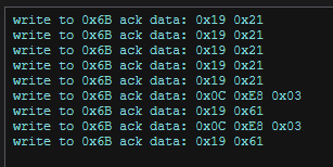
    Can you collect I2C logs for the period of time between connecting the AVHZy to right after you select the fixed option?

    I expect to see a write to the BQ device setting 0x03 to ~5V and for the BQ device to be enabled. Then, we should see roughly 5-V on J1(BQEVM).

    Something like this:

    Thanks and Regards,

    Chris

  • Hi Chris,

    On your 25751 what is the configuration of L2, L4, L5, L7

    I have L2 and L5 connected

    L4 and L7 are open

    Rick

  • Hi Rick,

    That might be it. I have L2 and L7 connected. L4 and L5 open.

    Was that how the board was default shipped?

    Thanks and Regards,

    Chris

  • Hi Chris,

    That was it!!!

    Thanks for hangin in there

    Regards,

    Rick