This thread has been locked.

If you have a related question, please click the "Ask a related question" button in the top right corner. The newly created question will be automatically linked to this question.

Powering up the TPS65930 with a PBC

Other Parts Discussed in Thread: TPS65930

Hi Gandhar,

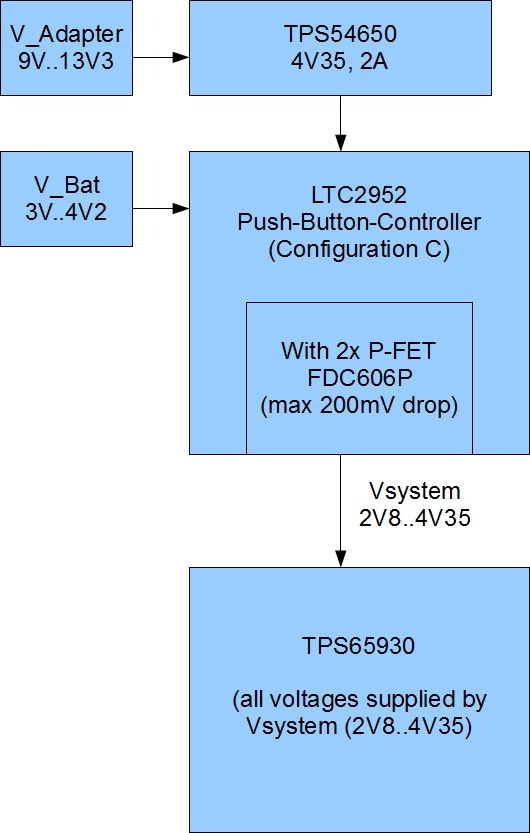
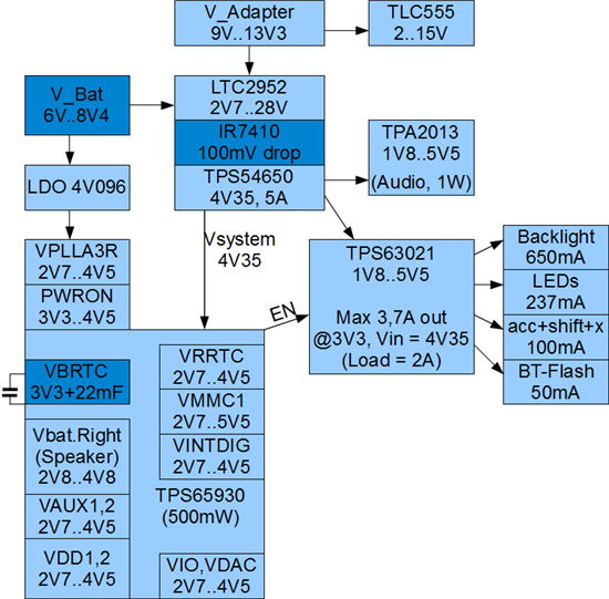
attached you see an overview how we would like to power up the TPS65930. It is not directly connected to the battery, there is a PBC before.

I think the application is very similar to cell phones, but I am not sure if this is a correct way of implementation, or if there is a better one.

Questions and comments are welcome.

Regards, Thomas


  • As long as TPS65930 gets the supply from a common rail, it is fine. 

    It is interesting to see your block diagram. I am used to seeing lot of handheld block diagrams with battery powering the PMIC. Such ones do show up once a while with this PMIC. 

    Please share your device application (if you can on the forum). If not then send me a note via friend message. Please note that for proper power on the inout to PMIC needs to be 3.2V (+/- 100mV). Good to have a 3.3V with min tolerance.

    Have you checked for TI equivalent of the LTC part? May be some TI field folks can help you. 

  • Hello Gandhar,

    thank you for your reply. Our device application is medical (patient monitoring), with blood pressure.

    You wrote that all supply should be in at one common rail. We are thinking to double the cell voltage, but then we need a regulator for the PMIC supply. (there is no other PMIC with all these functions including audio, capable to handle higher input voltages, is it?)

    Thats why we want at least supply the VPLL3AR-input with an LDO, also the PWRON for proper power on.

    Do you think this will work? (pls see new diagram)


    Regards, Thomas


  • I dont recommend this as there will be stress on the internal gates due to voltage differences at power up. This would cause reliability issues.


  • So any other idea how to power up the TPS65930 with two LiIon-cells in series?

  • This is a single cell PMIC. If you can guarantee that all cells of the series battery are at the same level and that supplies the PMIC without a potential difference then its ok. As I know this is extremely difficult, for Li-Ion there may be always some delta between the cells and this will not be good for the PMIC.

  • So as I understand even two parallel conducted lithium cells are not good for the PMIC? Dont think to, because the pack has only one voltage. Or why am I wrong?

    And is it also too much stress for the gates if only VPLLA3R is suppied by another, independent power source?

    I am thinking about supplying only VPLLA3R with an additional LDO, all other gates at one rail (3V..4V2).

    When I see the PMIC block diagram this should be possible. Do you agree, Gandhar?


    Regards, Thomas

  • If the pack has only one output voltage then the PMIC will see it as a single source. You may have to ensure that charging is ok and the pack always has a steady single output. 

    I do not recommend using VPLLA3R on another rail.