Tool/software:
We are exploring using Texas Instruments PN TPS61158DRVR as an alternate source for one of our designs that's already in production. We built prototypes using the TPS61158, ran the prototypes through our functional testers, and found that the new TPS61158 parts were being damaged during test by most (but not all) testers. We do have one tester where the boards pass test and TPS61158 performs as expected without being damaged, but re-testing the same previously passing board at another tester results in damaging the TPS61158 part. All testers still properly test and pass boards populated with the original backlight driver IC without damaging the boards. We suspect there must be a design error with how we've integrated TPS61158 into the design that's allowing for marginal proper operation on select testers (likely due to tolerances in the tester hardware). The damaged TPS61158 components have pins LX and VOUT shorted.
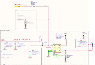
The tester applies a 1.5kOhm resistive load to the backlight driver IC and drives the backlight driver IC with a 100% duty cycle control signal. The edited schematic snippet below shows how we've designed the TPS61158 within the product, the voltages at select nets as provided by either the tester or the board itself during test, and how the 1.5kOhm load is applied by the tester. The 100% duty cycle signal is applied at net BKLEDPWM and is driven to the same voltage level as the VIN voltage (i.e. +3.15V). Note that the TPS61158 LX pin is labelled as SW by the U12 schematic symbol.
Are there any errors with how we have this circuit currently designed that would damage the TPS61158 part when attempting to drive a 1.5kOhm load at 100% duty cycle? What might cause pins LX and VOUT to short?