This thread has been locked.

If you have a related question, please click the "Ask a related question" button in the top right corner. The newly created question will be automatically linked to this question.

TLC5941-Q1: LED flickers during noise testing

Part Number: TLC5941-Q1

Tool/software:

Hello,

I am an FAE at a distributor that handles TI products.
I received the following question from my customer.

During EMS (immunity) testing, LEDs may flicker.
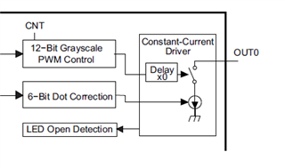
No PWM control. Maximum duty.
Used for brightness control with dot correction only.
As the interference level is increased, certain LEDs begin to flicker, and as the level is increased further, many LEDs flicker.
Since there are differences in resistance to interference depending on the LED port, we suspect that the interference component is being applied to the LED output, not the communication line between the CPU and the LED driver.
(Question)
Could flickering be caused by noise being applied to the constant current circuit?
If so, what measures can be taken?
Would inserting a capacitor between the output port and GND be an effective measure?
Are there any other possible causes for the LED flickering?

Best regards,

  • Hi Kaji,

    What kind of EMS test are you doing? Is it BCI or others? What's the VLED power? Is it caused by the DCDC?

    If you find the root cause is the power, you can take the following steps.

    If it's the noise to current, then you can add cap on the OUT channels.

    BR, Gracie

  • Thanks for reply.
    The standard is ECE-R10, which is immunity to electromagnetic radiation, and is ISO 11452-2 (ALSE method).
    The device has a plastic case and is not shielded.
    The phenomenon only occurs at a specific frequency (approximately 280 MHz).
    It is thought that the cable length and board size are affecting this.
    Please let me know if you have any suggestions for solutions.
    Best regards,

  • Hi Kaji,

    Do you have a layout file or schematic for me to review? Do you have cable shielded? What's the CLK frequency?

    BR, Gracie

  • Thanks for your reply.
    I will confirm the above with the customer.
    If a customer provides you with schematics and layouts, can you share them privately?
    The customer also shared the following information.
    VLED: 5V
    Approximately 7V is generated from the battery voltage via DCDC, and from there 5V is generated via LDO.
    However, this power supply circuit is on a separate board and is supplied to this board via a cable.
    3.3V is generated from 5V within the board via LDO, and this is used to power the microcontroller and LED driver logic section.
    Best regards,

  • Hi Kaji,

    Then We can try to isolate the problems into power and signal. Cables need to be carefully designed and also the VLED cap and VCC capacitor. Also, signal trace should have some ferrite beads and grounded well.

    If you want to send privately, you can just mail to me.

    BR, Gracie

  • Thank you for your reply.
    The customer has provided me with the following additional information.
    The cable is shielded, but since there is no metal case, the shield earth is connected to the GND on the board.
    The SCLK is approximately 4MHz.
    The customer has also provided me with a circuit diagram for the microcontroller and LED driver parts, so I will send this to you via private message.
    Best regards,

  • Hi Kaji,

    I have seen your private message and the schematic. Will check this and give you additional solutions later. Firstly we can see if the SCLK freq could be lowered and the slew rate could be lowered.

    BR, Gracie

  • Thank you for your reply.
    I received a question from a customer for your answer.
    >Also, signal trace should have some ferrite beads and grounded well.
    Is a signal trace a communication line with the microcomputer?
    Best regards,

  • Hi Kaji,

    Yes.