- Ask a related questionWhat is a related question?A related question is a question created from another question. When the related question is created, it will be automatically linked to the original question.
Tool/software:
Hi ,
I have used the recommended design in the Datasheet and have used in the feedback resistor value 10k and 57.6k for generating around 5.4 V.
and used 3.3u H with DC resistance of 140mOhm and Capacitors two 10uF X7R. I am also using a Diode at the output before the load.
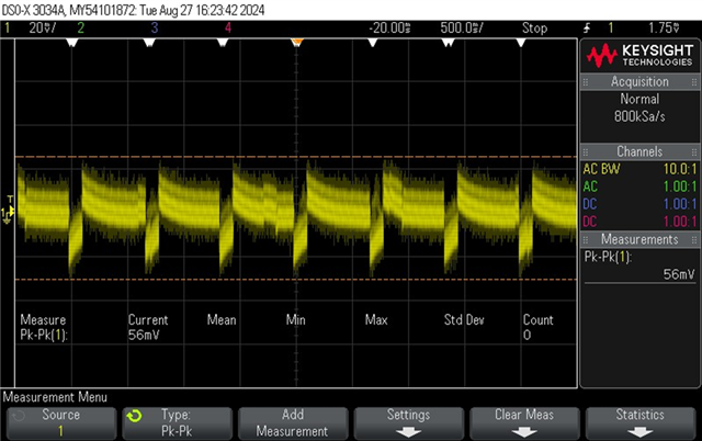
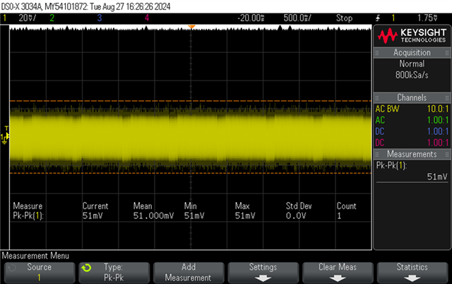
I can see ripple of around 200mV with load of around 40mA. I know TPS562201 works in PFM and has lower regulation in lower load region.
So I used TPS562208 which shows 38mV of ripple in Workbench simulation but I can see around 122mV.
It would be nice if you can suggest some improvements.