This thread has been locked.

If you have a related question, please click the "Ask a related question" button in the top right corner. The newly created question will be automatically linked to this question.

LMG1210: Seeing 11.74VDC on VDD and GaNFET always active.

Part Number: LMG1210

Tool/software:

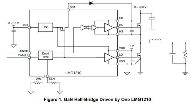
I am utilizing the LMG1210 GaN Driver in IIM configuration with the intent to drive an EPC8002 GaN FET. I have the circuit configured such that there are 3 voltage rails that can be chosen for the GaN Drain or an external signal that is intended to be drained to GND. Essentially, based on the configuration of the populated R00 jumpers, the LMG1210 chip can drive the EPC8002 GaNFET either high-side or low-side. Let me know if you have any further questions about the schematic.

I am having a few issues occuring using the below design:

- On high side application, the GaN FET is always active, regardless of input at HI

- Upon testing, the VDD pin was showing 11.74VDC with reference to power GND.

DipTrace Schematic - 0038B0411_SIMPLIFIED.pdf

  • Hello,

    When 12V is applied to VIN, you are seeing 11.74V on VDD? The internal LDO may be damaged. Do you see the same issue with multiple devices?

    Also, the high side switching will not function as HS is floating and there is no path for the bootstrap cap to charge.

    Thanks,

    Walter

  • I have replaced the device twice, and I am still seeing 11.74 on VDD. What are the implications of leaving both DHL and DLH floating? I have no use for the internal LDO otherwise.

    Per part U1.5, the Bootstrap diode is capacitively coupled to HS via a feedthrough cap. This was implemented IAW the LMG1210EVM-012 datasheet (SNVU572) on page 5. Is the way that I implemented the feedthrough cap not acceptable for my intended application? Thank you for the quick reply!

  • Hello,

    Since you have EN/HI and PWM/LI connected together, DLH must be connected to VDD to select the independent input mode. DHL can be left floating or tied to VDD or ground in independent mode. If both inputs are connected together in PWM mode, the device will be disabled every time the PWM signal is low.

    The high side switch uses a level shifter and bootstrap cap and diode in order to reference the HO output voltage to HS.

    This document describes how the bootstrap circuitry works. https://www.ti.com/lit/an/slua887a/slua887a.pdf

    A charging path from HS to ground is needed when the high side switch is off in order to charge the boot cap. This is commonly through a low side switch. Since your circuit does not have a charging path from HS to ground, a floating supply or low side switch is needs to be added for high side switching. The gate driver output voltage needs to be shifted to the proper level in order to turn on the FET.

    Thanks,

    Walter

  • I wonder if I might have found the issue. You referenced, on page 3, that DHL should be floating, GND, or VDD and that DLH should be tied to VDD for IIM. On page 15, however, the following table is laid out.

    This is the table that I followed for my design, which has DHL tied to VSS and DLH tied to VDD for IIM on page 15 of the datasheet. Is there some guidance as to which is the correct configuration for IIM?

    Copy that on the bootstrap circuitry though. I realize I in fact did not have a path to ground, so I will have to change the in the next design draft. Interestingly, it seems as though there is very little in the way of documentation specifically for IIM. Thanks for the detailed replies.

  • Hello,

    Figure 16 leaves out that DHL can also be tied to VDD for IIM. Your schematic is configured correctly for IIM

    Taking a second look at the schematic I believe the issue is you do not have a ground node connected to VSS.

    VSS is the device's ground node and so since there is no ground connection, the device is not turned on and 11.74V is coming through the LDO to the VDD pin.

    IIM is explained in this table and timing diagram. In IIM, LO is independently controlled by LI and HO is independently controlled by HI. 

    Thanks,

    Walter