This thread has been locked.

If you have a related question, please click the "Ask a related question" button in the top right corner. The newly created question will be automatically linked to this question.

TPSM33625: 36Vin Rating Buck

Part Number: TPSM33625
Other Parts Discussed in Thread: LM76002, TLV62569,

Tool/software:

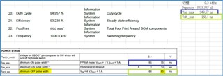
Team, Customer is looking for 36V derating for below condition and FuSa.

5.5Vin to 5Vout/2.1A

Ambient 85degree

Vin:5.4~5.6V

Vo:5V/2.15A

We tried the WEBENCH, but it doesn't work. also the Tj could be over spec. Is there any alternative one? The power Module is better, or you can recommend the converter.

Regards

Brian

  • One more question, what's the max. duty cycle of TPSM33625?

    Regards

    Brian

  • Hi Brian,

    The issue is not with heat but with the lower limit. When operating at 5.4 VIN, the part will be subject to dropout, but this phenomena is not covered in the scope of the webench model. The max duty cycle of this device is dependent on your operating conditions. Please see this thread and section 7.4.3.5 of the datasheet for more details. In any case, it does not look like 5.4 VIN will allow for a 5 VOUT.

    Can you please outline what is needed of this design (AUTO or FPWM, Switching Frequency) and I can recommend a new part.

    Thank you,

    Joshua Austria

  • so, TPSM33625 doesn't work with this condition, right?

    Here please find the device requirements. 

    FPWM

    Switching freq > 400K

    5.5Vin to 5Vout/2.1A

    Ambient 85degree

    Vin:5.4~5.6V

    Vo:5V/2.15A

    Low cost device

    Regards

    Brian

  • Hi Brian,

    At 400 kHz and 2.1 A out, a 5.4 VIN - 5 VOUT may be difficult for a Wide VIN part to support without entering dropout. Can I ask why a Wide VIN part is being considered instead of a likely better fit with the Low VIN profile bucks at TI?

    Thank you,

    Joshua Austria

  • That is for the FuSa power consideration.

    The power tree is :

    24Vin to 5.5Vout by LM76002

    5.5Vin to 5Vout by TPSM33625 (This one needs > 24V voltage derating against the 24V is shorted to 5.5Vin rail inside the LM76002 as it's not FuSa compliant device)

    5Vin to 3.3V/1.3V by TLV62569/

    Regards

    Brian

  • Also, customer has done the test on the TPSM33625EVM with 5.5Vin to 5Vout/0.5A-1.5A. However, we found the random switching on the SW node pin. Is that normally? what is the reason it's not regular switching?

    Is TPSM33625 able to do the 5.5Vin to 5Vout/0.5A-1.5A? What else converter or power module with >28V rating you suggested? thanks. 

    thanks. 

    TPSM33625 EVM 實測結果.pptx

  • Hi Brian,

    Like noted before, the device's datasheet states that this condition is not supported, so your results may vary when operating the part like this. The random switching is due to the device not having sufficient input voltage to support its output and thus the part operates in dropout where the device switching frequency folds back to try and support the high duty cycle required without violating its timing characteristics as specified in the datasheet EC table. 

    Is there a reason that the customer cannot do a 5.4 -> 3.3 or 1.3 V application? I believe this device has a better chance at consistently supporting this at load.

    Thank you,

    Joshua Austria

  • Hello Joshua,

    Thanks. Regarding to the SPEC of TPSM33625, with the condition of the 300KHz freq setting, 5.4Vin - 5.5Vin and 5Vout, the calculated min off-time > 85nS that is specified in d/s. Why is it violating the SPEC? We're confused about it! Is the reason drop voltage caused by internal Rds(on) of the high side SW? How about the resistance of high side switch and Inductor? Very Thanks. 

    The reason behind is related to the FuSa SIL3 requirement as i mentioned early. The 5.5V to 5V converter is for the single fault shorting with 24V from LM76002 not to damage the downstream devices. 

    One more questions, customer is more interested in TPSM33625 on this design. Could you help to feedback on below question!

    1. If output voltage is set at 5V, and output current load is 200mA, 500mA, 1A and 1.5A, how about the minimum input voltage at 300KHz freq?

    2. also, If input voltage is set at 5.5V, how about the max. output voltage with current load 200mA/500mA/1A/1.5A?

    Customer would like to know the device capability and optimize the design. Very thanks. 

    Regards

    Brian

  • Hi Brian,

    Yes you are correct, there are numerous internal factors within the device's operation that contribute to dropout. Efficiency will also increase your duty cycle further for example. This thread shows how efficiency affects duty cycle, which works as a better approximation than using Webench's duty cycle. 

    For your system requirements here are some quick calculations:

    D = VOUT/(VIN*EFF) = 5/(5.4*.93) = 0.9956

    Toff = (1-D)/FSW = (1-.9956)/300000 = 14.7 nS < Toff min = 85 nS

    Now for your questions. These values will have to estimated based on the efficiency curves in the datasheet. You can take a look at table 7-6 for a understanding of some of the tested values for minimum and maximum output voltages given common input voltage ranges. 

    We normally do not provide these calculations as these numbers are heavily use-case based. We recommend bench testing of your customer's system to determine these numbers.

    Thank you,

    Joshua Austria