This thread has been locked.

If you have a related question, please click the "Ask a related question" button in the top right corner. The newly created question will be automatically linked to this question.

LM5175: Single direction peltier driving - current control

Part Number: LM5175
Other Parts Discussed in Thread: LM5176, LM5177, LM51772

Tool/software:

Hello,


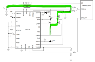
I am looking to design a TEC driver using a LM5175, but the ouput is controlled in current (not in PWM, to reduce the EMC radiation).
My ouput will be at 45 V, 15A, so this is why I need an external FET driver.

Is there a way to control the output in current (from 0A to 15A) with a 0-3V DAC controler ??

Thank you,

Thibaud

  • Hi Thibaud,

    there is an application report based on the LM5176 on using a TEC element.

    This might be a good starting point.

    Bidirectional TEC Driver Design for 40-W TEC

    I also have not understood why you would like to use current control or how you would like to control.

    So if the above report does not help, I would need some more details to understand the setup you would like to build.

    Best regards,

     Stefan

  • Hi,
    Thank you for the TEC Driver design LM5176. This can be the one I am looking for.
    I presume that I can increase the output power by adjusting the Power Mosfet ?
    And I can also limit the output current ?
    Does the output voltage is linear or pulsed ?

    My initial question was to control the Peltier module by current and not by voltage, in order to regulate the cold in a linear way and not in PWM.
    So I was looking for a current driver for example, to control the ouput current from 0A to 15A.
    For example, 2A to have a little bit of cold, and 15A to make a lot of cold.

    Regards,

    Thibaud

  • Hi Thibaud,

    yes, the output power can be increased with adjusting the MOSFETs.

    You can use the average current limit to limit the current but this is not for a dynamic adjustment.

    You might use the LM5177 or LM51772 with the same approach as the LM5176 but use the Current Monitor to measure the current and based on that adjust the output voltage of the Power stage. With that approach you could get a current regulation.

    Have not understood this question: Does the output voltage is linear or pulsed ?

    Best regards,

     Stefan

  • Hi Stefan,
    Thank you for your help.
    about the question of output linear or pulsed, I was thinking about the Led Driver.
    As it controls the ouput with an high current, but usually the output is a PWM (pulsed) , but I do not want this.
    Thibaud

  • Hi Thibaud,

    this is an SMPS, so that output is fixed not pulsing. As you typically have a large output cap, doing dynamic output voltage changes with large voltage steps, like for  PWM, it is not easy.

    Best regards,

     Stefan

  • Hi Stefan,

    I have one last question about the current way in the design.

    Does it goes through the H bridge ?  This is to make the component selection as 15A will cross the TEC driver.

    Thank you,

  • Hi Thibaud,

    the LM5176 circuit works as SMPS and provide with using the inductor a defined output voltage.

    It is not sinking current as you have drawn above but uses the 4 MOSFET depending on the required operation mode as BUCK, BuckBoost or Boost.

    Best regards,

     Stefan