Other Parts Discussed in Thread: TIDA-010247, BQ76942, LM5168
Tool/software:
Hello experts,
We are initiating a design for a BMS for cells upto 32S using BQ76952. We are basing the schematic off of TIDA-010247 by Mr. Ryan Tan. I am hoping this thread can serve as a support thread for the development of this design.
Although TIDA-010247 is based on BQ76942, our design will be using BQ76952 and the Li-ion cell we are using will be having a max voltage of 4.2V and hence the total system BAT voltage will be ~135V. In general I am trying to understand what components or section I will need to redesign because of the higher system voltage.
So, here are the questions we have currently:
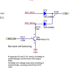
- We cannot be using the power section from the reference design. Do you have an alternate part from TI's portfolio for the same?
- Can you tell the function of D1 and D4. Should I be sizing it for the higher voltage?
Many thanks,
Abhijith