This thread has been locked.

If you have a related question, please click the "Ask a related question" button in the top right corner. The newly created question will be automatically linked to this question.

TPSM84209: 15V to 5V design with TPSM84209

Part Number: TPSM84209

Tool/software:

Hi,

I am using TPSM84209 for a 0.4 A application. Input voltage is 15 V and output voltage is 5 V.

1- I have a 100 uF electrolyte and a ceramic 100 nF near the pins of the IC. Do I need to increase the size of the ceramic capacitor? I thought with having only 0.4 A, the ripple in the input cap is small and does not need to be size higher.

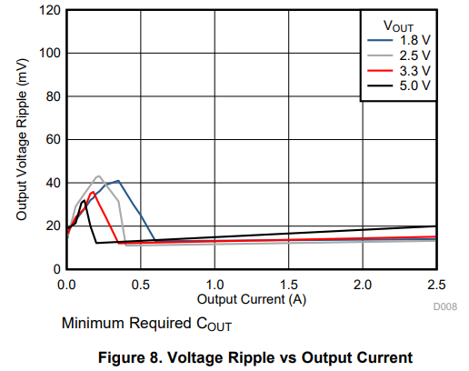
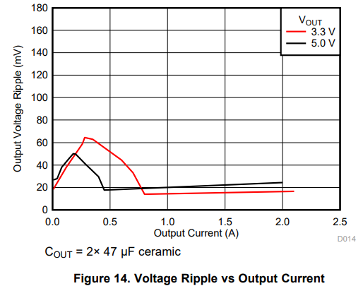
2- Will pulse skipping happen with these specs? In the graph in the datasheet, it looks like pulse skipping will happen for any current with these voltages.

3- Does pulse skipping result in output voltage overshoot?

4- What size of copper plane do I need given that we have ~0.3 W of power dissipation? In the datasheet, 63mm*50mm is mentioned.

Thanks,

Marzi

  • Hi Marzi,

    My Colleague Bella will reply to you later.

    Colin

  • Hi Marzi

    Please reserve the 100nF ceramic cap, you can add one 2.2uF ceramic Cin.

    Pulse skipping will not result in output voltage overshoot. The Vo_ripple can be larger than the ripple under CCM mode.

    I didn't find the fsw vs load curve in the datasheet, but seen from the Figure 8 and Figure 14, it's related with the Cout selection.

    the 63mm*50mm is based on the EVM. With this copper size and the 4-layer PCB, The RθJA parameter is 32.7℃/W. In our application the load is only 0.4A and the power dissipation is small. Should not have concern about the thermal performance. 

     BTW, we have new devices TPSM861252/TPSM861257 which are 17V ,1A module. 

    Thanks and best regards.

  • Thanks Gui. I do not have room for a 2.2 uF ceramic cap. What issues will I face if I only use a 100 nF cermaic cap (along with my 470 uF electrolyte which is not right at the pins of the IC)?

    Regarding the thermal performance, with a 6mm*5mm plane will the thermal performance be ok? how can I calculate the junction temperature?

  • Hi,

    Gui He will reply to you tomorrow. 

  • Hi Marzieh

    It's ok not to have the 2.2uF ceramic cap since you already place 470uF electrolytic Cin, Electrolytic capacitor has larger ESR and ESL, the Vin ripple voltage might be larger, There would be no problem if you check the Vin and the Vin_ripple is not higher than you spec.

    The 100nF ceramic cap is necessary in order to filter the high-frequency noise caused by the fast switching of the buck converter.

    For the thermal performance, The RθJA value is related to the PCB size, the layout arrangement and the copper layer. ( Information about the RθJA and thermal metrics: Semiconductor and IC Package Thermal Metrics)

    The datasheet has the RθJA value under the condition of the EVM(o a 63 mm × 50 mm, 4-layer PCB with 2 oz for top& bottom and 1oz for inner layer) for your reference. Under this condition, the Tj_rise would be 15.6℃ under 15V->5V,0.4A. Referring to the Webench Tool https://webench.ti.com/power-designer/switching-regulator/customize/219?VinMin=15&VinMax=15&O1V=5&O1I=0.4&base_pn=TPSM84209&AppType=None&Flavor=None&op_TA=30&origin=pf_panel&lang_chosen=en-US&optfactor=3&Topology=Buck&flavor=None&VoltageOption=None 

    Thanks and best regards.