This thread has been locked.

If you have a related question, please click the "Ask a related question" button in the top right corner. The newly created question will be automatically linked to this question.

BQ40Z50-R2: Cell balancing not working

Part Number: BQ40Z50-R2

Tool/software:

Hello,

We are trying to get external cell balancing working in our system, but having problems.

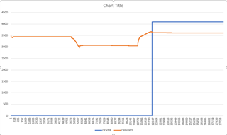
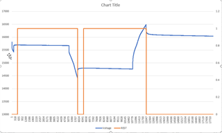
Our system is a series-stack of 4 cells and, to check cell balancing, Cell 3 is more discharged compared to the other cells to create an obvious imbalance. For this experiment, we started with the system at UpdateStatus=0x6 (in fact, we loaded the data memory .gg.csv file from the end of a successful learning cycle), then tried to get the gauge to make a Qmax update and cell-balancing calculation via a rest-discharge-rest sequence, then charged the cells to full to (hopefully) see cell balancing activate. In particular, here's what we did:
1) A quick discharge (just to distinguish the upcoming rest).
2) A rest for 5.5 hours (to allow a DOD1 measurement).
3) A long discharge, of about 44% RSOC (to satisfy the 37% delta capacity requirement).
4) A rest for 5.5 hours (to allow a DOD2 measurement, and hence a Qmax update and a cell-balancing calculation).
5) A charge to full (to see the cell balancing turn on).
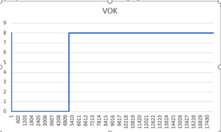
The idea here was to make the system perform a Qmax measurement (via steps 2 and 4) and set UpdateStatus=0xE, then do a full charging and see cell balancing turn on. However, when we do this experiment, no cell balancing occurs--the OperationStatus[CB] flag does not ever go to 1. In fact, ITStatus[QMAX] never goes to 1, meaning no Qmax measurement is made during step 4 (we also confirmed that UpdateStatus never goes to 0xE, but stays constant at 0x6). What are we doing wrong? From our understanding, if nothing else the gauge should make a Qmax-qualified OCV measurement after 5 hours in relax, so we should have gotten Qmax-qualified measurements during our two 5.5 hour rests. But for some reason, that didn't happen.

For reference, we have included the .log file, and also the starting .gg.csv file, for the above run.

Thanks,
- charlie

run_learning_cycle_20240823_161155_trim.log1run_learning_cycle_autoexport_20240823_161155.gg.csv

  • Hi Charlie,

    Looking into the log file, I have concerns that the Flat Region condition of the Qmax update is being broken, hence why an update is not occurring. If possible, can you please send the .srec of the gauge so we can confirm whether this is the issue?

    Regards,

    Anthony

  • Hello Anthony,

    Sure, please find attached the .srec file of the gauge. I took it just now on 8/29, whereas the experiment was run back on 8/23, but we have not updated the chemistry since then, so hopefully the .srec is still indicative. Speaking of the flat region, we did notice that ITStatus[OCVFR] did fire, but only after charging (i.e., step 5): during the rests of steps 2 and 4--when we were hoping to get a Qmax update--it remained low.

    As another possibility, the Technical Reference mentions an "offset error" condition that prevents Qmax updates (SLUUBK0B, Section 6.4.2). However, we didn't understand how to check the offset error. The reference says it "accumulates during time passed" suggesting it's a time-varying value, but then the reference gives the equation CoulombCounterDeadband/SenseResistor, which would seem to a ratio of constants? We were confused. Nonetheless, we did turn on the data memory autoexport for this run--at 5 min intervals--so have a whole gaggle of .gg.csv files. If the offset error can be calculated from those files, and you let us know how to make that calculation, we can independently check the offset error on our side.

    Thanks,

    - charlie

    20240829_gauge_srec.zip

  • Hi Charlie,

    Thank you for sending the ,srec, please give us until early next week to check this over. Regarding the CC Deadband/Sense Resistor value, this value is being compared between the time between the two OCV measurements. The design capacity value this is compared to can be altered to fit the same time period between the two OCV measurements. We will check for this as well.

    Regards,

    Anthony

  • Hello Anthony,

    Did the srec provide any insight to the problems we're having getting cell balancing working? Do you have any theories or experiments that I can perhaps check on my side? We do still have the autoexported .gg.csv files at 5 min intervals, so I can also analyze those if it'll help. Let me know!

    Thanks,

    - charlie

  • Hi Charlie,

    After looking into the .srec, I believe that the reason that the Qmax is not updating in the second cycle is due to the voltage of Cell 3, which is less than the other cells. In the relax after charge where OCV measurements would be taken for Qmax updates, the voltage of this cell is within the flat region which is most likely invalidating the update, along with not allowing your Update Status to change. I believe if cell 3 was at the same voltage as the other cells this issue could be avoided.

    Regards,

    Anthony

  • Hello Anthony,

    A couple questions:

    1. Hmm, why didn't GaugingStatus()[OCVFR] bit fire during this time? Does it require multiple cells to be in the flat region to fire?

    2. How do I find the flat region for my cells? Is it somewhere in the srec file, or is it maybe stored somewhere in the .gg.csv file? If I know the voltage limits of the flat region, then I can redesign the experiment to keep Cell 3's voltage depressed (to test the cell balancing), yet make sure that when I come to second cycle, none of the cells are in the flat region.

    Thanks,

    - charlie

  • Hi Charles,

    1. Hmm, why didn't GaugingStatus()[OCVFR] bit fire during this time? Does it require multiple cells to be in the flat region to fire?

    I believe the OCVFR bit does fire at this time. In the image above, the OCVFR can be observed being set once the voltage enters this region.

    2. How do I find the flat region for my cells? Is it somewhere in the srec file, or is it maybe stored somewhere in the .gg.csv file? If I know the voltage limits of the flat region, then I can redesign the experiment to keep Cell 3's voltage depressed (to test the cell balancing), yet make sure that when I come to second cycle, none of the cells are in the flat region.

    When the ChemID is programmed, this contains the flat region values specific to the chemistry being used. This is an interesting case currently because the voltage from cell 3 does not seem to be entering the flat region based on what is seen in the .srec. Can you please attempt this test with the [LFP_RELAX] bit in IT Gauging Configuration off and see if this effects the results?

    Regards,

    Anthony

  • Hello Anthony,

    By "during this time", I had actually meant during the 2nd rest step, corresponding to roughly times 5707-10779 on your plot. Just to make sure we're on the same page, I'm defining the stages as:

    Times ~318-5073: 1st rest

    Times ~5073-5707: Discharge (significant, >37%)

    Times ~5707-10779: 2nd rest   <--- expected Qmax meausurement during this step

    Times ~10779-12047: Charge to full

    Times ~12047+: Rest after charging   <--- at beginning of this step, OCVFR fires

    We had expected the gauge to make a Qmax measurement during the 2nd rest, but it didn't. If this is because Cell 3 was in the flat region, then why didn't OCVFR fire during the 2nd rest step (t=5707-10779)? Why did the OCVFR firing instead get delayed until after the full charging (t=12047)?

    Anyway, I will go ahead and re-run with Settings::IT Gauging Configuration[LFP_RELAX]=0, and send the log files when it's done.

    Thanks,

    - charlie

  • Hi Charles,

    We had expected the gauge to make a Qmax measurement during the 2nd rest, but it didn't. If this is because Cell 3 was in the flat region, then why didn't OCVFR fire during the 2nd rest step (t=5707-10779)? Why did the OCVFR firing instead get delayed until after the full charging (t=12047)?

    For a typical learning cycle, the first Qmax update should occur after the Charge to Full stage. The document below gives the step by step of what to expect in each part of the learning cycle:

    https://www.tij.co.jp/jp/lit/an/slua903/slua903.pdf?ts=1726063208477 

    Since the flat region is a relatively small voltage range, voltage of cell 3 during the second rest is not close to the flat region, hence why I believe it did not trigger.

    Regards,

    Anthony

  • Hello Anthony,

    Sorry for the delay. I have rerun the experiment with Settings::IT Gauging Configuration[LFP_RELAX]=0; please find attached the .gg.csv and the log file for the run. However, I didn't see much change in the results: we still don't get Qmax measurement during the 2nd rest.

    Hmm, looking over your comments, I get the feeling I'm misunderstanding something fundamental. So here, let me explain what we're trying to do, and you let me know if we're missing something. We have previously done a complete learning cycle, going to UpdateStatus=0x6 and then doing another charge-relax-discharge-relax cycle to get to UpdateStatus=0xE as discussed in the Conclusion section of SLUA903. Following that, we set UpdateStatus back down to 0x2, as also discussed in SLUA903.

    We wanted to test cell balancing. Given that SLUA903 says to set UpdateStatus=0x2 before saving the Golden File, we assumed that--in the field--the gauge would start with UpdateStatus=0x2, or its equivalent 0x6 (which is just 0x2 plus GAUGE_EN=1). So we started our experiment with UpdateStatus=0x6. Our understanding was that, after that, it would only require another Qmax measurement to push the gauge to UpdateStatus=0xE, which would subsequently enable cell balancing. Hence our experiment: start with UpdateStatus=0x6 and the battery at a higher SOC, then discharge it enough to get a Qmax measurement (which happens during our experiment's 2nd rest). With the Qmax measurement, the gauge will set UpdateStatus=0xE, which will activate the cell balancing calculation. Finish with a final charging, then, to see the cell balancing at work!

    Does this make sense as a valid way to test cell balancing? I note that, in order to get UpdateStatus to 0xE, we do NOT do a full charge in our experiment, but instead do a partial discharge. We figured this would be more indicative of how people would use the system in the field: plug it in and try it out. Are we required to do a full charge in order to get UpdateStatus=0xE?

    Some other questions:

    -- I guess the question of why there is no Qmax measurement during the 2nd rest remains. From what I understand from your comments, it's not the flat region, right?

    -- We did notice that our gauge registers a small discharge current of 3-4 mA when at rest. This is clear in the attached .log file, and can also be seen in the original .log file: in both, zooming in on the current shows that it's not 0 during rest, but in fact bounces around between 0 and -4 mA. This clearly violates the 4-uV/s requirement for Qmax measurement. But then in theory the Qmax measurement should happen regardless after 5 hours, and we don't see that happening either. Nonetheless, could this varying discharging current during rest be a hint at why Qmax measurement isn't occurring during the 2nd rest?

    -- And speaking of the current during rest, is this magnitude of discharge current typical? It seems high to me, but I don't have much experience with battery gauges. Should we be looking to debug that and get that discharge current either lower in absolute value, or more constant and less dynamic?

    Thanks,

    - charlie

    run_learning_cycle_20240911_012815_trim.zip

  • Hi Charles,

    Does this make sense as a valid way to test cell balancing? I note that, in order to get UpdateStatus to 0xE, we do NOT do a full charge in our experiment, but instead do a partial discharge. We figured this would be more indicative of how people would use the system in the field: plug it in and try it out. Are we required to do a full charge in order to get UpdateStatus=0xE?

    Thank you for the clarification. I believe this is a valid way to go about trying to achieve Update Status = 0x0E, however I believe the partial discharge could be causing the issue here. For standard Qmax updates, the amount of passed charge for the gauge to create the Qmax Update is 37%, however for learning cycle values it's 90%, hence why we recommend you charge to full and discharge to empty.

    In the last document sent, there are two viable rest periods (before the same OCVFR bit becomes set), however there is still no Qmax update occurring. Is it possible to try the test (after loading the update status 0x06 file to the gauge) and running a full charge - relax - discharge to empty - relax cycle to see if this is able to force the update status to 0x0E?

    -- I guess the question of why there is no Qmax measurement during the 2nd rest remains. From what I understand from your comments, it's not the flat region, right?

    There are two rest periods happening prior to that, so I do not believe this is causing the issue being seen.

    -- We did notice that our gauge registers a small discharge current of 3-4 mA when at rest. This is clear in the attached .log file, and can also be seen in the original .log file: in both, zooming in on the current shows that it's not 0 during rest, but in fact bounces around between 0 and -4 mA. This clearly violates the 4-uV/s requirement for Qmax measurement. But then in theory the Qmax measurement should happen regardless after 5 hours, and we don't see that happening either. Nonetheless, could this varying discharging current during rest be a hint at why Qmax measurement isn't occurring during the 2nd rest?

    In this case, the gauge is clearing the 4uV/s condition since the gauge is setting the [REST] bit. However, for the second relax, another bit to observe is the VOK bit, which depicts whether the OCV measurement taken during relax qualifies for the Qmax calculation. This bit is set during charge/discharge and cleared when the measurement qualifies. In this situation, it is not clearing for the second relax:

    This could be caused by the passed charge percentage idea talked about earlier since the disqualification conditions can be found below:

    -- And speaking of the current during rest, is this magnitude of discharge current typical? It seems high to me, but I don't have much experience with battery gauges. Should we be looking to debug that and get that discharge current either lower in absolute value, or more constant and less dynamic?

    I believe the discharge current here is OK. When choosing discharge and charge currents, they are typically based on the capacity of the cell. In this case, a 4900mAh cell is being used, and a 1A discharge is being used, which is roughly C/5, which is pretty normal. Same goes for the charge.

    Regards,

    Anthony

  • Hello Anthony,

    Thanks for all the clarifications! I think I understand your proposed experiment: you suspect it might be something with the amount of passed charge, that it's supposed to be 37% but maybe the gauge is thinking it needs to be higher. For example, the gauge might be thinking it's the 90% required during the learning cycle. So we can try doing that: we can try getting a passed charge of 90% and see if the gauge will transition from 0x6 to 0xE. Ok, I'll code that up and run it.

    In the meantime, a clarification: in my final question asking "is this magnitude of discharge current typical?", I meant the 3-4 mA of current I was seeing during the rest periods (it's a negative current, hence my calling it a "discharge current"). That current-during-rest seemed a bit high--I would have thought it to be closer to 0--and it bounces around a lot. So I was just wondering if that amount and dynamism of current-during-rest is expected, or if I should be debugging for a current leakage problem somewhere?

    Thanks,

    - charlie

  • Hi Charlie,

    Thanks for all the clarifications! I think I understand your proposed experiment: you suspect it might be something with the amount of passed charge, that it's supposed to be 37% but maybe the gauge is thinking it needs to be higher. For example, the gauge might be thinking it's the 90% required during the learning cycle. So we can try doing that: we can try getting a passed charge of 90% and see if the gauge will transition from 0x6 to 0xE. Ok, I'll code that up and run it.

    Understood, please share the results when received.

    In the meantime, a clarification: in my final question asking "is this magnitude of discharge current typical?", I meant the 3-4 mA of current I was seeing during the rest periods (it's a negative current, hence my calling it a "discharge current"). That current-during-rest seemed a bit high--I would have thought it to be closer to 0--and it bounces around a lot. So I was just wondering if that amount and dynamism of current-during-rest is expected, or if I should be debugging for a current leakage problem somewhere?

    Normally, if the gauge is able to enter relax even with the standby current, then it shouldn't be an issue. However, there are functions within the gauge that allow for the accumulated current at this time to be allowed to effect the SOC measurement in real time, known as the smoothing functionality. This can be found in the IT Gauging Configuration under [SMOOTH] where more details can be found. If this function is not used, then the accumulated change in charge will be applied once the gauge exits relax. However, 3-4mA should not be a big issue unless the relax periods are very long, so we can look into this if you would like.

    Regards,

    Anthony

  • Hello Anthony,

    Attached please find the results of the requested run, including both the .gg.csv file (at start) and the .log file. A couple notes regarding the setup:

    -- This run starts with a brief discharge to empty (the battery started near empty), rests, then does a full charge, 2nd rest, then full discharge, 3rd rest.

    -- In order to speed things up, I shrunk the precharge charging region and increased the LV charging region by changing AdvancedChargeAlgorithm/VoltageRange::ChargingVoltageLow from 2900 mV to 2750 mV. I don't think this should affect the results.

    -- LFP_RELAX is set back to 1 again. I don't know if this will change the results.

    Looking at the results, it seems that I still do not get a Qmax measurement. This time, it would seem that OCVFR turns on towards the end of the full charge, and then never lets go: it remains high through 2nd rest, full discharge, and 3rd rest. I'm not sure why this would be, seeing as how the cells pass through a variety of voltages and, if they were in the flat region, should have left it at some point during the full discharge.

    Thanks,

    - charlie

    run_cell_balancing_DSG_fullCHG_DSG_20240920_111305.zip

  • Hi Charlie,

    Thank you for sending those files over. I can also see that the OCVFR is being triggered when it seems like the cell voltages are not in the flat zone. Let me reach out to our firmware team to see what other instances could be causing this to happen. Ill provide an update when recieved.

    Regards.

    Anthony