This thread has been locked.

If you have a related question, please click the "Ask a related question" button in the top right corner. The newly created question will be automatically linked to this question.

TPS65987D: TPS65987 Program from MCU via I2C, not SPI Flash

Part Number: TPS65987D
Other Parts Discussed in Thread: BQ25750, TPS65987,

Tool/software:

Hello, 

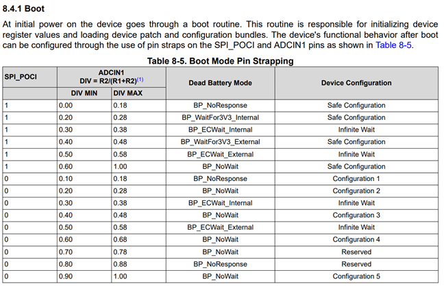
I'm developing a device which uses the TPS65987 to negotiate a DFP contract from a power supply to charge my systems pack through a BQ25750. 

Our board does not have an SPI Flash and we are planning to use our MCU to store the TPS65987 FW and upload it on device power up. We don't have any strict startup time requirements so this seems/seemed like a suitable option. However, it looks like the much more standard configuration is to program via an SPI flash at POR. 

From reading other posts, it seems like this is at least possible. If anyone can provide some documentation on how to do this that would be great. 

Thanks in advance!

  • Hi Ryan,

    We don't have a dedicated patching over I2C guide for TPS65987D, but you can refer to our technical reference manual (TRM) attached. The TRM has a section describing all of the I2C commands the MCU needs to send the TPS65987D to patch FW directly over I2C.

    6761.TPS65987DDH8DH_slvubh2b.pdf

    Order of commands:

    PTCr - Patch Reset

    PTCs - Patch Download Start

    PTCd - Patch Download (For Each 64 Byte Block)

    PTCq - Patch Query (Query Patch Status Anytime During The Sequence)

    PTCc - Patch Download Complete

    Additionally, please ensure the TPS65987D device boot configuration is set up properly using ADCIN1. What you select as the boot configuration will depend on whether you wish the system to begin sinking power before the MCU loads FW to the TPS65987D, etc... Refer to the datasheet for more details.

    Best,

    Alex

  • Hey Alex, thanks so much for the answer. 

    1. We have the device configured for config 3 and BP_NoWait. My understanding is that the device should enter a contract with a 20V power supply at 3A if available without any configuration flashed to it. Correct?

    2. WRT the i2c update, will I export the high and low regions of the patch from the Application Customization Tool and then start writing from address 0x2000 in 64byte chunks? Then I will change the start address (incrementing by 64 bytes for each write) for each additional data block?

    3. Analyzing the i2c signal it would seem that the ucpd chip is using bit stretching quite often in both 100kHz and 400kHz i2c modes. Is this normal?

    4. I also see in the data sheet that the ucpd chip requires 4us before the next bit is sent after it releases the SCL line but as far as I can tell our STM32 i2c peripheral does not have any provisions to add this delay. Thoughts?

  • Hi Ryan,

    Today is a TI holiday, I will get back to you about this this week. 

    Thanks,

    Alex

  • Hi Ryan,

    1. Correct. The PD will do a 5-20V sink contract with the far-end, depending on what the connected device source capabilities are, and also enable the sink path.

    2. Since you are doing patching the PD directly over I2C, you'll generate the low region (full header) binary only. The full flash image is only for storing in external EEPROM or flash memory. You'll only need that one low region binary, and you'll transfer the data in consecutive 64B blocks over I2C using the PTCd command.

    3. Some clock stretching is normal. If you are concerned, you can send an I2C log and we'll take a look.

    4. STM32 is quite popular so its I2C peripherals should be compatible. If you see any issues related to this, we can take a look. Otherwise no concerns.

    Best,

    Alex