Tool/software:
Hi!
We have a design based on LM3409 IC. The original idea was to adjust the output current with a PWM signal on the EN pin.
After the first batch we started to test the circuit, but the currents were not close to the desired value. And it was not linear as well.
The first test was with a 1kHz pwm, but it instantly burnt out one of the LEDs we are using. Then we changed to 64 kHz.
The schematic is the following:

The design parameters and calculations are inculded in the led_driver.m file. The script was tested with the datasheet examples, it seemed to be working. (It is attached at the end of the post)
The problems we are facing are:
1) The PWM duty cycle is not linear to the current consumption.
2) In different leds the output current with the same duty cycle is different.
3) Even with EN pulled to Vin, and trying to control with Iadj pin, the output current at 1V is around 50mA.
Any help is appriciated! Thank you!
Coff = 470; %in pFVadj = 1.24; %in VVin = 24;Vo = 22; %in VRsns = 0.08; %in OhmIled = 1.3;ilpp=0.085;iledpp = 0.020;rd = 2;eta =0.95;vinpp=0.500;iled=1.3;fsw = 515;rdson = 0.012;Vfd = 0.5;
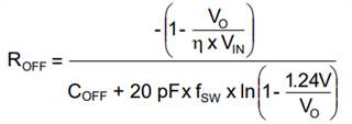
Roff = -(1-Vo/(eta*Vin))/(490*1e-12*fsw*1e3*log(1-1.24/Vo))/1000Roff=2.400toff = -(Coff+20)*Roff*log(1-(1.24/Vo))fsw = 1e6*(1-(Vo/(Vin*eta)))/toffton = 1/(fsw*1e3)-toff*1e-9Cin_min=iled*ton*1e9/(1e3*vinpp)L = Vo*toff/(1000*ilpp)L=18ilmax=iled+ilpp/2Rsns=Vadj/(5*ilmax)Rsns = 0.18iled = Vadj/(5*Rsns) - ilpp/2ilpp = Vo*toff/(1000*L)Zc = 1e3*rd*iledpp/(ilpp-iledpp)Co_min=1e6/(2*pi*fsw*Zc)itrms = iled * sqrt(Vo/(Vin*eta)*(1+1/12*(ilpp/iled)^2))Pt = itrms^2*rdsonid=(1-Vo/(eta*Vin))*iledPd=Vfd*id