This thread has been locked.

If you have a related question, please click the "Ask a related question" button in the top right corner. The newly created question will be automatically linked to this question.

TPS5450: Inquiry about typical application circuit

Part Number: TPS5450

Tool/software:

Hello,

My customer has some questions about the following application circuit of the TPS5450.
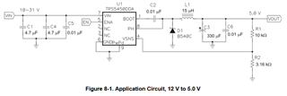
Q1. Would it be a problem if I use electrolytic capacitors instead of ceramic capacitors for C1 and C4 at the input?

Q2. If electrolytic capacitors are used for C1 and C4 and the ripple current of the power supply input to these capacitors is higher than the allowable ripple current of the capacitors, is it possible that this will cause problems for the TPS5450 or surrounding components?

Thank you.

JH

  • Hello

    C5 will need to be a ceramic.

    And at least one of C1 or C4 should be ceramic.

    The ceramics provide a low inductance path for the fast switching 

    currents of the converter.

    Then, large electrolytics can be used in addition, if desired.

    The RMS ripple current can be calculated as shown in the data sheet.

    Your input capacitors should be rated for this current.  

    If the input capacitors are not rated for the ripple current, they may overheat and/or become damaged.

    Thanks