This thread has been locked.

If you have a related question, please click the "Ask a related question" button in the top right corner. The newly created question will be automatically linked to this question.

LMG3422R050: Current consumption with 12Vdd

Genius 17695 points
Part Number: LMG3422R050

Tool/software:

Hi Experts,

Can you help us evaluate this concern from customer using LMG3422R050 in switched-capacitor circuit?

See attached the description of my question in details to this email. This is confidential.

LMG3422R050_TI.pdf

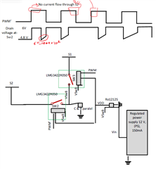
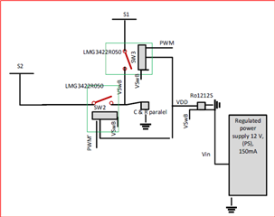
How much current should I consider for the 12V bias of the LMG3422R050 gate driver when using a 12V DC-DC converter to provide it?

Additionally,

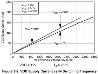
Is 12-V bias of LMG depends on the amount of voltage at the drain of GaN devices, S1 and S2? Additionally, I looked at the LMG3422R050 datasheet. There is a curve showing the current consumption of the LMG at different frequencies. For higher frequencies, the current consumption Increases.

For high frequency about 1 MHz, how much current should I consider for VDD-12-V bias voltage?

Thank you for your guidance.

Regards,
Archie A.

  • Hello Archie,

    Apologies for the delay, I have picked up this question and started reading through your attachment, I will need some time to give you an appropriate answer.

    Please give me till early next week and I will get back to you.

    Thanks,

    Zach 

  • Thank you, Zach.

    Here is additional information provided:

    I am providing PWM through FPGA and digital isolator. 

    I reduced the PWM frequency to 100kHz. The 12V bias power supply with 90mA current limit didn't drop. To verify the LMG3422R050 functionality, I checked fault, OC, and temp output for each LMG3422R050. Fault' output remains at high. However, OC' output remains low and Temp output turns on for one PWM period,10us, every 160us. 
     
    The current limit at S1 and S2 is 30mA. 
    Would it be possible to let me know Why short circuit occurred in the circuit? 

    After completing test at 100kHz, I will increase the frequency and current limit at 12V bias to verify the functionality.

    Regards,
    Archie A.

  • Thank you for the additional info,

    I have some thoughts about the power supply used related to the device current consumption, I will summarize and share tomorrow.

    Thanks,

    Zach

  • Hello Zach,

    Any update on this?

    Regards,
    Archie A.

  • Hi Archie,

    Zach is out of office today. He will be back in office this coming week.

    Best,

    Kyle 

  • Hello Kyle,

    Any update? Thank you.

    Regards,
    Archie A.

  • Hey Archie,

    I'm going to break up this reply into three parts: LMG342x datasheet specifications, the concerns with customer test setup, and how TI measures current consumption on VDD supply.

    LMG342x Datasheet specs:

    VDD quiescent current is typically 700 uA, this assumes 12V Vdd, Vin 0 or 5V, and no current consumption from LDO5V. Also, figure 5-9 shows the supply current vs IN switching frequency:

    These both assume that no current is pulled from the LDO5V pin. These values are what we expect to see from the VDD pin, therefore if we see something much higher, it most often is related to some peripheral circuitry pulling more current than expected, or improper operating conditions.

    Customer test setup:

    Customer states that power supply is outputting 30mA of current and DC-DC converter is consuming 14mA. There is very likely some current coming from the power supply, but using the power supply to measure VDD current consumption will be very inaccurate. I highly recommend that the customer use a current probe or some accurate current sensing scheme. Additionally:

    - How is the 14mA of current from the DC-DC converter measured? If this value is from the datasheet, it could be possible that the converter is consuming more current.

    - Is there any circuitry connected to the LDO5V pin?

    - Is it possible for the customer to remove the DC-DC converter and supply VDD using power supply directly? This will help us narrow down the problem device.

    How TI measures current consumption on VDD supply:

    1. Two devices are connected in half bridge

    Note: A dedicated supply LS_VDD for low side for accurately measure the voltage and current (Supply have kelvin connection for accurately forcing the voltage). The HS have a dedicated isolated supply. On the HS isolated supply we connect 5V at the input and it generate 10V at the output.  This will generate 10V for the HS_VDD. And isolator +5V_H is generated by external LDO.

    1. Complimentary PWM signals for low and high sides coming from a pattern generator with high side signals pass through isolator and the LS_IN no isolator is used.
    2. Measure the LS_VDD power consumption during the half bridge switching.

    Note: IVDDOP test the LS_IVDD current is measured with the scope.  A current probe is connected at the LS_VDD supply.  The scope is set to run at 6.25GS/s, and measure the current waveform and capture the average of multiple cycles.  

    Diagram:

    Please let me know what follow-up you have,

    Zach

  • Hi Zach,

    Thank you for the detailed response. Here is the follow up:

    How is the 14mA of current from the DC-DC converter measured? If this value is from the datasheet, it could be possible that the converter is consuming more current.

    14mA is measured in the lab using multimeter in series with the DC-DC converter Input while the output of DC-DC converter is disconnected from the rest of the circuit.

    Is there any circuitry connected to the LDO5V pin?

    Yes, the LD05V is connected to the two digital isolators, ISO7760FDBQ, which provide PWM for the LMGXX. I copied the exact schematic with the same component values as proposed in the LMG342XEVM-04X User Guide.

    1. Can I remove C10, C2, R3, and R4 from the circuit if I connect VCC1 directly to the 5V power supply?
    2. Is the rest schematic correct in my application? Do I need to do any modification?

    Is it possible for the customer to remove the DC-DC converter and supply VDD using power supply directly? This will help us narrow down the problem device.

    I will try and let you know.

    1. Would it be possible to let me know if there is any way to determine the issue with the LMG3422R050 in the below case:

    The fault signal was at a high level, and I was able to measure the expected output voltage. However, after working on the circuit for about 30 minutes, the output voltage fluctuated significantly. I didn't change anything in the setup. To find the problem I added two resistors—10 Ohm and 0.02 Ohm—in series with S2 and S1, respectively, to limit the current and make it possible to measure the voltage variation at the drain of SW2. I found that the LMG3422R050 shuts down randomly when the capacitor is charging. Sometimes, when the PWM signal is at a high level and is supposed to be drawing current, the GaN transistor inside SW2 switches off, causing the drain voltage to return to 6V, the same as at S1.

    The circuit specifications are as follows:
    power supply at S1: 5V, 60mA
    power supply at S2:6V , 110mA
    PWM freq : 100KHz

    The output waveforms are attached below.

    Thank you.

    Regards,
    Archie A.

  • Hi Archie,

    As discussed, I will review this update early next week and follow-up in this thread.

    Thanks,

    Zach

  • Hello Zach,

    The follow up above has been solved already. No need for further action. Here is the new query:

    Just I would like to ask you to let me know the following questions:
    1. Does HV-S1 affects HV-S2 if I use just one digital isolator to provide the PWM signals for both switches? I've  just connected LD05 pin of SW2 to the power pin of the digital isolator. However, when I increase the voltage at Hv-s1  with out touching HV-S2 , the power supply at HV-S2 increases from 5V to 5.5V. I checked LD05 pin of both switches, both shows 5V.
    2. what may cause the above problem? because there is no trace outside both switches to connect HV-S1 and HV-S2.
    Thank you in advance for your support.
    Regards,
    Archie A.